Blackmagic Design published the 150-page DaVinci Resolve 21 New Features Guide in April 2026. This edition converts the complete guide to Markdown for easier searching, linking and section-by-section reading, with all 189 illustrations hosted locally. The original English feature descriptions are preserved.
- Download the official PDF
- Converted range: PDF pages 7–150, from Introduction through Codec Support
- Images: browser-friendly JPG files hosted locally
Introduction
DaVinci Resolve 21 introduces a new Photo page, which enables colorists and photographers to use Hollywood’s most advanced color tools for still photos.
The new Photo page lets you import and manage photographs, integrating with the color page for node based grading. Use primary color correction, curves, qualifiers, power windows and node editor to adjust color in artistic ways across an entire project. Plus, you can use a DaVinci color panel to adjust multiple parameters at once.
Other updates include new AI tools such as IntelliSearch for fast content searching, CineFocus for focal point adjustment and tools for facial refinement.
The Krokodove toolset adds over 70 new graphics to Fusion, Fairlight folders simplify audio track management, plus there are improvements to keyframing, MultiMaster trim passes, layer list node graphs.
The new features guide introduces these features and will be included in the DaVinci Resolve reference manual after the public beta.
We hope you enjoy the new features in DaVinci Resolve 21.
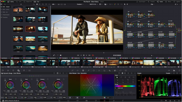
Color page DaVinci Resolve 21
Photo
Photo Image Editing Now Fully Integrated Within DaVinci Resolve.
Photo Page
DaVinci Resolve 21 introduces a powerful new Photo page. This page is designed for users to manage, organize and grade their photo projects using all the powerful color management and grading tools available natively in Resolve. It is the first and only image editing software fully integrated with a video editing pipeline.
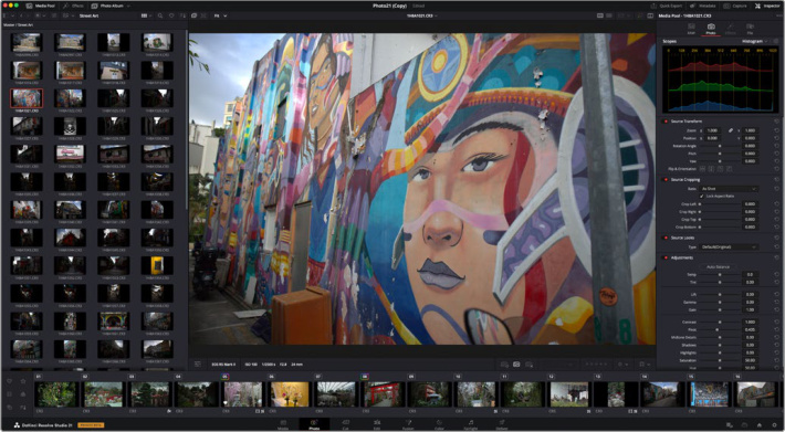
Photo Page
The Photo page is primarily a photo editing application, but with deep integration into the rest of DaVinci Resolve’s effects and toolset it opens up more creative possibilities than still image editing normally allows. Using Photo Albums you can pass full resolution stills into the Cut, Edit, Color, and Fusion pages for additional processing.
The Photo page features a full image management pipeline including tagging, favorites, ratings and photo album collections. In addition you can tether your camera to the Photo page, and capture images and control your camera settings live. Using the new IntelliSearch feature, you can let the AI analyze your images, then search for them based on content, objects, people, colors, and more. The Photo page comes with a large effects library built in, with several of the most powerful Resolve FX and Fusion FX ready to use.
The addition of the Photo page to DaVinci Resolve lets you move fluidly between photos, video editing, color grading, VFX and audio post, all in real time.
NOTE: All grades and effects for still images within albums are applied at the source level. This means that the grades for your stills are shared across all the albums within a project similar to remote grades.
Using the Photo Page
The Interface Toolbar
At the very top of the Photo page is a toolbar with buttons that let you show or hide different parts if the user interface. These buttons are as follows from left to right:

Photo Page Toolbar


Media Pool: Opens or hides a smaller version of the full Media Pool page, allowing access to all the images used in the project.
Effects Library: Opens or hides the repository of all transitions, generators, and effects, available to use in the Photo page.
Photo Album: Opens the Photo Album at the bottom of the interface.
Quick Export: Opens the Quick Export Dialog to simply deliver an export of your photos.
Metadata: Shows or hides the Metadata Editor.
Capture: Shows or hides the capture interface that lets you capture still photos to your computer tethered to your camera.
Inspector: Shows or hides the Inspector which lets you edit both RAW and debayered photo parameters, and edit any effects properties.
The Media Pool
In the Photo page, the Media Pool contains only the still image media that you’ve imported for editing into the project at hand, as well as all of the albums that you’re going to be using to organize your photos. Unlike the Media Pools found on other pages, it will not show any video, audio, timelines, or effects clips. They are still there of course, just hidden from view as the Photo Page is dedicated to still images only.
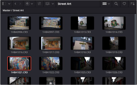
The Media Pool in the Photo Page
Clicking on the Bin list in the upper left shows a hierarchical list of bins used for organizing your photos, which is also used to organize your albums. By default, the Media Pool consists of a single bin, named “Master,” but you can add more bins as necessary to organize timelines and clips by clicking on the Bin List and choosing + Add Bin. You can rename any custom bin by double-clicking on its name and typing a new one, or by right-clicking a bin’s name and choosing Rename Bin.
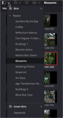
Clicking on the Bins icon, opens the bin list dropdown.
The browser area shows the contents of the currently selected folder. Every still photo, bin, and album appears here. You can create as many albums as you need within a single project.
The Media Pool can be displayed in either Thumbnail, or List view. In List view, you can sort the contents by any one of a subset of the total metadata that’s available in the Metadata Editor of the Media page.
Importing Photos Into the Media Pool on the Photo Page
While adding photos to the Media Pool in the Media page provides the most organizational flexibility and features, if you find yourself in the Photo page and you need to quickly import a few photos for immediate use, you can do so in a couple of different ways.
To use the Import Media icon in the Photo page Media Pool:
1 With the Photo page open, click on the Import Media list icon at the top of the Media Pool.
2 Choose from the following options:
Import Media: Opens a file requestor to import selected photos.
Import Media Folder: Opens a file requestor to import all photos inside the selected folder.
Import from Photos (macOS only): Opens the Photos app in macOS and lets you select photos for import.
Import from Lightroom: Imports an Adobe Lightroom Catalog.
Import Blackmagic Cloud Folder: Lets you link a Blackmagic Cloud folder and imports the photos stored within.
To use the Import Media command in the Photo page Media Pool:
1 With the Photo page open, right-click anywhere in the Media Pool, and choose Import Media.
2 Use the Import dialog to select one or more photos to import, and click Open. Those Photos are added to the Media Pool of your project.
Bins and Smart Bins
There are actually two kinds of bins in the Media Pool, and each appears in its own section of the Bin list. Here are the differences between the each kind of bins:
Bins: Simple, manually populated bins. Drag and drop anything you like into a bin, and that’s where it lives, until you decide to move it to another bin. Bins may be hierarchically organized, so you can create a Russian dolls nest of bins if you like. Creating new bins is as easy as right-clicking within the bin list and choosing Add Bin from the contextual menu.
Smart Bins: These are procedurally populated bins, meaning that custom rules employing metadata are used to dynamically filter the contents of the Media Pool whenever you select a Smart Bin. This makes Smart Bins fast ways of organizing the contents of projects for which you (or an assistant) has taken the time to add metadata to your photos using the Metadata Editor, adding exif data, keywords, comments and description text, and myriad other pieces of information to make it faster to find what you’re looking for when you need it. To create a new Smart Bin click the bin list and choose + Add Smart Bin. A dialog appears in which you can edit the name of that bin and the rules it uses to filter clips, and click Create Smart Bin.
Searching the Media Pool
Clicking on the magnifying glass icon in the toolbar opens a search field, where you can look for specific image names. However using the new IntelliSearch feature described elsewhere in this guide lets you use AI technology to provide comprehensive, near instant search for people and objects that you type into this field.
Effects Library
All effects that you can add to your photos, are found in the Effects panel. The Effects panel shows a hierarchical list of all of the different effects and filters that are available, sorted by category.
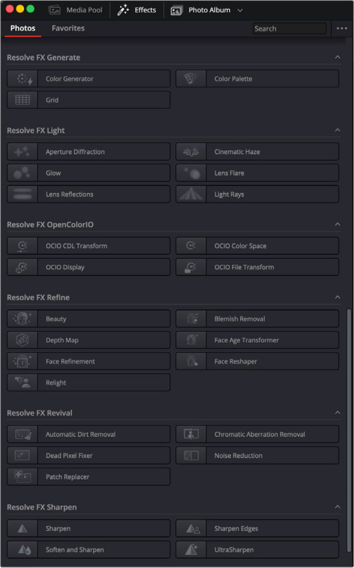
The Photo Effects library
To preview an effect before placing it on a photo, ensure that “Hover Scrub Preview” is checked in the Effects option menu, then simply hover your pointer over any thumbnail in the Effects tab and move it across the thumbnail. The effect will preview in the Viewer using its default parameters.
To activate a specific effect on a photo, simply drag the thumbnail of the selected effect to a photo in the Album. To adjust the effect’s parameters, open the Effects tab in the Inspector.
You can search for a particular effect by typing in the search bar at the top of the Effects Library. Pressing Shift-Space will bring up the Effects Search dialog in the Photo page. If you have a photo selected, clicking on the effect in the search list will apply that effect to the selected photo.
You can search for effects and transitions using Category Names as a search term. For example, searching for “Stylize” will bring up all the Resolve FX under the Stylize section. You can also search for effects using the language set in DaVinci Resolve > Preferences > User > UI Settings, in addition to English.
NOTE: All Effects are described in detail in the Resolve FX section of the DaVinci Resolve Reference Manual
Photo Albums
This tab opens up the Photo Album at the bottom of the interface. Like their physical analog, Photo Albums in the Photo page are where you store and organize collections of still images. In DaVinci Resolve you can equate them to a special type of timeline, built from user curated stills.
Organizing your media pool images into photo albums is critical to getting the most out of the still photo capabilities in DaVinci Resolve 21. Photos are resolution and frame rate independent, while timelines are not. The Photo page uses the Photo Album as its central organizational container, and it allows your photos to interact with the rest of the pages in DaVinci Resolve.

The Photo Album Interface
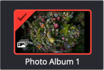
A Photo Album in the Media Pool
To create a Photo Album:
Right-click in the Media Pool and select New Photo Album from the context menu.
In the main menu select File > New Photo Album.
To add an image or images to a Photo Album:
1 Select an image or group of images in the Media Pool.
2 Right-click on an image and select Add Photo(s) to Album
3 The selected photos will be added to the current Photo Album
To delete an image or images from a Photo Album:
1 Select an image or group of images in the Media Pool.
2 Right-click on an image and choose Delete Selected.
3 The selected photos will be removed from the current Photo Album
Once an album has been created and populated you can use the Photo Album toolset to quickly organize, sort and label still images for further use in DaVinci Resolve. You can add flags, colors, and tags to images in the Viewer, then use the filter tools in the Photo Album to organize and sort them.
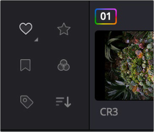
The Photo Album filtering icons
Filter By:
The Icons will highlight white if they’re active.


Tags: Clicking on this icon lets you filter the photos in the album based on tags. Right clicking on the icon lets you choose the criteria by Good Take, Untagged, or Rejected flags, or a combination of those tags.
Rating: Clicking on this icon lets you filter the photos in the album based on rating. Right clicking on the icon lets you choose the criteria by equal to, is less than or equal to, or is more than or equal to, and then the exact star rating you want to use as the base criteria.
Flags: Clicking on this icon lets you filter the photos in the album based on flags. Right clicking on the icon lets you choose which color flag or flags you want to use as the criteria.
Color: Clicking on this icon lets you filter the photos in the album based on clip color. Right clicking on the icon lets you choose which color or colors you want to use as the criteria.


Keywords: Clicking on this icon lets you filter the photos in the album based on keywords. Right clicking on the icon lets you choose which keywords you want to use as the criteria.
Sort Photos: Clicking on this icon toggles the sort order of the photos in the album either in ascending or descending value. Right clicking on the icon lets you choose which metadata value you want to use as the sort criteria.
In addition Photo Album thumbnails show icons that tell you if certain operations have been applied to the photo.
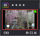
The Photo Album thumbnail icons
Photo Album list of thumbnail icons and their meanings:
Rainbow Rectangle around image number: Means that a RAW or Photo operation has been applied.
Star Rating: The user rating assigned to the clip. You can click this rating to change it.
Flag: In the upper right of the thumbnail, a colored flag icon shows you what flags have been assigned to the photo.
Color: The small colored capsule shape in the lower right, shows you what colors have been assigned to the photo.
Heart or X: This shows whether a favorite or rejected tag has been assigned to the photo.
Image Format: In the lower left under the thumbnail, this shows the image format of the photo.
FX: In the lower right under the thumbnail, this shows that an effect has been applied to the photo.
Transform: The rectangle icon in the lower right under the thumbnail shows that a transform operation has been applied to the photo.
Crop: The overlapping angles icon in the lower right under the thumbnail shows that a crop operation has been applied to the photo.
Advanced Filtering
If you need more advanced Filtering options, you can sort and filter photos by using the dropdown menu next to the Photo Album tag. You can filter based on attributes such as Graded vs. Ungraded photos, People, Photos modified in the last X hours, etc.
Using Photo Albums in other DaVinci Resolve Pages
Photo Albums can be used to move still photos at their native resolution between the different pages in DaVinci Resolve. This means that in addition to the Photo page, you can use the tools in the Cut, Edit, Color, and Fusion pages on your still photos as well.
The Viewer
The Photo Viewer lets you take a detailed look at one specific photo while you’re editing it, as well as containing its own toolset to work with your photos.
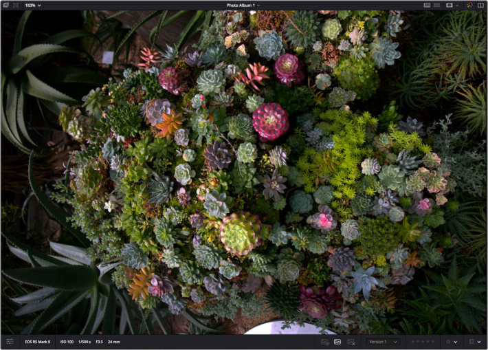
The Photo Viewer
Top Toolbar

The Photo Viewer top toolbar
Photo Album: Shows the selected image.
Capture Live View: Opens the live view when shooting tethered.
Zoom %: Lets you choose the zoom level of the viewer.
Album List: Shows the current Album. Click on the dropdown menu to directly open a recent album.
Single View: Opens a large single viewer.
Lightbox: Enters Lightbox mode that shows resizable thumbnails of all the images in your album.
Viewer Guides: Opens guides for different aspect ratios, safe areas, and user customizable rulers and guidelines.
Bypass Color and Fusion: Bypasses any Color or Fusion effects that may have been applied. You can select to bypass only Color, or only Fusion in the dropdown menu.
Lightbox
Clicking the Lightbox icon replaces the single photo view, with a series of resizable thumbnails for each photo in your album. This lets you see larger views of multiple photos, and gives you a general overview of what’s in your album.
You can also select any image and grade it live while seeing the results update across the whole collection in real time.
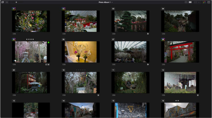
The Photo Viewer Lightbox
Hand Mode
Holding down the H key in the viewer enters hand mode. When hand mode is active, the image view is scaled to 100% and dragging the hand around the viewer moves the picture. Double click on an area to examine individual pixels. Double click again to zoom to fit image to viewer.
Bottom Toolbar

The Photo Viewer Bottom toolbar
Tools: Opens the Transform, Crop, and Effects Overlay interfaces.
Exif Data: Shows the ISO, Shutter Speed, Aperture, and Lens metadata.
Favorite: Tags the image as a favorite, with a small heart icon.
Untag: Removes the favorite or reject tag from an image.
Reject: Tags the image as rejected, with a small x icon.
Version Selector: Choose another version of the image you’ve saved.
Rating: Lets you assign a one to five star rating for the image.
Color: Lets you assign a color tag to the image. Color tags can be used for organizational operations in the other pages of DaVinci Resolve.
Flag: Lets you assign a color flag to the image. Flags can be used for organizational operations in the other pages of DaVinci Resolve.
Transform Toolbar
When you select Transform, onscreen transform controls appear that let you directly manipulate the image in the Viewer. You can drag anywhere within the clip’s bounding box to adjust pan and tilt, drag any diagonal corner to proportionally resize, drag any top/bottom/left/right side to squeeze or stretch width or height, or drag the center handle to rotate.

The Transform Toolbar
NOTE: When using the onscreen controls, the tool will always show the original photo size underneath the transform grid. This is designed so you can still see the areas outside the frame while you’re making adjustments. Closing the tool bar again will activate the transform operation and apply it to your image.
The onscreen controls also correspond to the following editable parameters, which are also editable in the Video Inspector.
Toggle Button: Lets you enable or disable an effect without losing whatever custom adjustments you’ve made.
Zoom Width and Height: Allows you to blow the image up or shrink it down. The X and Y parameters can be linked to lock the aspect ratio of the image, or released to stretch or squeeze the image in one direction only.
Zoom Link: Activate this lock to link the width and height zoom together to keep the same proportions in a zoom operation. Deactivate this lock to zoom width and height separately.
Position X and Y: Moves the image within the frame, allowing pan and scan adjustments to be made. X moves the image left or right, and Y moves the image up or down.
Rotation Angle: Rotates the image around the anchor point.
Pitch: Rotates the image toward or away from the camera along an axis running through the center of the image, from left to right. Positive values push the top of the image away and bring the bottom of the image forward. Negative values bring the top of the image forward and push the bottom of the image away. Higher values stretch the image more extremely.
Yaw: Rotates the image toward or away from the camera along an axis running through the center of the image from top to bottom. Positive values bring the left of the image forward and push the right of the image away. Negative values push the left of the image away and bring the right of the image forward. Higher values stretch the image more extremely.
Flip Image: Two buttons let you flip the image in different dimensions.
Flip Horizontal control: Reverses the image along the X axis, left to right.
Flip Vertical control: Reverses the clip along the Y axis, turning it upside down.
- Reset: Lets you reset every parameter within a particular category of controls to the default settings.
Crop Toolbar
The Photo page has a set of onscreen controls you can use to directly crop the image in the Viewer. Each side of the image has an individual handle for cropping just that side. These parameters are also editable in the Video Inspector.

The Crop Toolbar
NOTE: When using the onscreen controls, the tool will always show the original photo size underneath the crop grid. This is designed so you can still see the areas outside the frame while you’re making adjustments. Closing the tool bar again will activate the crop operation and apply it to your image.
Toggle Button: Lets you enable or disable an effect without losing whatever custom adjustments you’ve made.
Aspect Ratio: Lets you choose common aspect ratios for still photo and video formats, or chose your own custom ratio. Defaults to As Shot, which is your camera native aspect ratio.
Lock Aspect Ratio Activate this lock to lock the currently selected aspect ratio for any crop operations. Unlock to crop to a freeform aspect ratio.
Crop Left, Right, Top, and Bottom: Lets you cut off, in pixels, the four sides of the image.
Reset: Lets you reset every parameter within a particular category of controls to the default settings.
Open FX and Fusion Overlays
If you’ve applied an Open FX or Fusion Effect that has onscreen viewer controls, you can access those controls here, by pressing the appropriate icon.
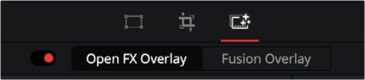
The Overlay Toolbar
Adding Versions in a Photo Album
One of the more useful features of a Photo album is it’s versioning feature. You can make adjustments to your photo, save it as a version, then try something radically different on the same image, knowing that the original version is safely stored. You can save as many versions of an image as you like.
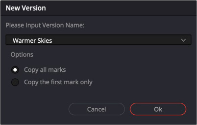
The New Version dialog Box
It’s easy to create a version, simply make your edits, right click on a photo in the Photo Album and select New Version from the context menu. This will open up the New Version dialog box, where you can add a descriptive name for your version and then press the OK button.
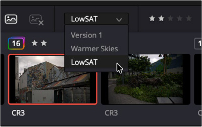
The Version Dropdown at the bottom of the Photo Viewer
It’s equally easy to switch versions as well. Any saved versions will be available in the exact same right-click context menu you created it with. In addition there’s a simple dropdown selector at the bottom of the Photo Viewer you can use.
IMPORTANT: Only the currently selected version will be exported in Quick Export and the Deliver page, all other versions will be ignored.
Quick Export
Quick Export opens a delivery window that’s designed specifically for still images. You simply select the image format you want to use on the left side, then enter the file’s parameters on the right then click export.
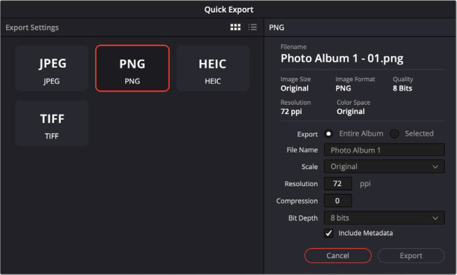
Quick Export tab in the Photo Page
The exact file parameters shown will depend on the image format that you choose, but the common ones are:
Export: Choose between exporting the entire Album of photos, or just the ones that have been selected.
File Name: You can add text to be used as a file name prefix.
Scale: Select either original resolution, or a percentage reduced resolution for smaller file sizes.
Include Metadata: Check this box to include the photo’s metadata in the final image.
TIP: If you need greater control over your photo export, you can use the Deliver page tools instead.
Metadata
In the Photo page, the Metadata Editor opens in the same place as the Inspector. When you select a photo in the Media Pool or Album, its metadata is displayed within the Metadata Editor. If you select multiple clips, only the first clip’s information appears. The Metadata Editor’s header contains uneditable information about the selected clip, including the file name, directory, duration, frame rate, resolution, and codec.
Because there are so very many metadata fields available, two drop-down menus at the top let you change which set of metadata is displayed in the Metadata Editor.
Metadata Presets (to the left): If you’ve used the Metadata panel of the User Preferences to create your own custom sets of metadata, you can use this drop-down to choose which one to expose. Surprisingly enough, this is set to “Default” by default.
Metadata Groups (to the right): This drop-down menu lets you switch among the various groups of metadata that are available, grouped for specific tasks or workflows.
The heart of the Metadata Editor is a series of editable fields underneath the header that let you review and edit the different metadata criteria that are available.
Capture
This tab opens up the Capture Live View interface for tethered shooting directly from your camera into DaVinci Resolve. This lets you instantly transfer your shots to the Media Pool or a Photo Album for editing, client review, or just to see your image in higher resolution on a larger screen.
Setting up Camera Tethering
First, you will need to setup Camera Tethering on your camera. Each make and model of camera has different methods for doing this, so please reference your camera’s manual for specifics. Next you will need to connect your camera to your DaVinci Resolve Workstation via a USB cable.
Finally, your local computer may require some additional setup:
BETA NOTES
As of this Beta, only Canon and Sony cameras are currently supported for tethered live capture.
macOS: Both Canon and Sony cameras are supported natively.
Windows: Canon cameras are supported natively. Sony cameras are supported, but require additional software to be installed: https://creatorscloud.sony.net/catalog/en-us/ ie-desktop/index.html
Linux: Tethering is not supported.
iPad: Tethering is not supported.
If you’re having trouble with your camera connecting to DaVinci Resolve there are some troubleshooting tips:
Make sure there are no other programs running that connect to the camera automatically, like photo editing applications.
Sometimes you may need to restart DaVinci Resolve to connect to your camera.
Once your camera and computer system are setup, pressing the Capture tab will automatically connect to your camera and pressing the Capture Live View icon at the top of the viewer will take you to the Capture Live View interface.
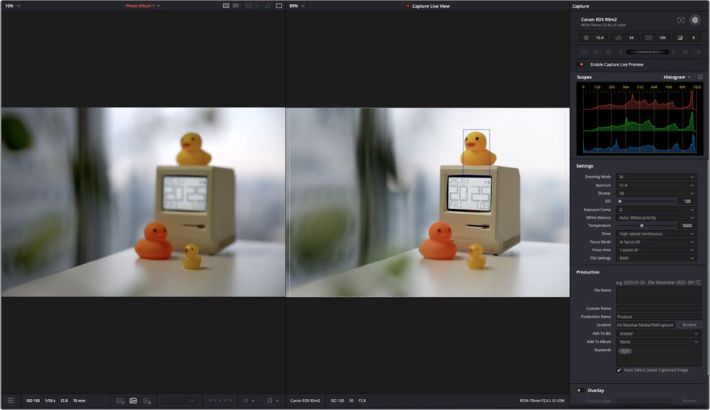
Capture Live View
In the right hand column, the capture controls appear, depending on your camera model, you will be able to change your camera settings right from the capture interface. You can control settings like aperture, shutter speed, ISO and Exposure compensation right from the top toolbar. Directly underneath lets you adjust focus by rotating the wheel, or pressing the direction buttons. Further down in Settings, you can adjust more advanced camera settings. Camera settings that are not supported will be grayed out.
To the immediate left will be the Capture Live View that will update in real time from what your camera is seeing, including onscreen displays like focus boxes and focus peaking.
The display to the far left is the last photo that you captured, so you can see the difference between it and your current shot setup. At any time you can pause the Live View by toggling the Capture Live View slider.
Once your camera is showing what you’re after, you can capture the image by pressing the shutter release button in the upper right of the capture controls.
Capture
This toolset lets you control your camera and capture images.
Camera Name: The model of camera that is connected to capture.
Half Press: Click this icon to send a half-press signal to the camera, often used to lock autofocus before firing the shutter.
Shutter Release: Click this icon to activate the camera’s shutter release, taking a photo.
Aperture: Shows the currently selected aperture of the camera lens.
Shutter Speed: Shows the currently selected Shutter Speed of the camera.
ISO: Shows the currently selected ISO of the camera.
Exposure Compensation: Shows the currently selected exposure compensation of the camera.
AutoFocus: Click this icon to set the autofocus.
Control Wheel: Depending on which parameter is active and controllable, you can use the control wheel and the forward and backwards controls to adjust that parameter.
Enable Capture Live Preview: Activate this toggle switch to turn on the Live Camera Preview in the viewer.
Scopes
The scopes here are identical to those in the Inspector. The selected scope will update in real time from the camera data.
Settings
These settings allow you to directly control the tethered camera from the Capture interface. Depending on your specific camera some or all of these modes may be disabled.
Shooting Mode: Set a shooting mode for the camera, common modes are A (aperture priority), S (shutter priority), P (program), and M (manual). There can be different options depending on your specific camera.
Aperture: Sets the lens’ aperture.
Shutter: Sets the camera’s shutter speed.
ISO: Sets the camera’s ISO
Exposure Comp: Sets the number of stops of for the camera’s exposure compensation.
White Balance: Set’s the camera’s white balance setting preset.
Temperature: Set an exact white balance temperature in degrees kelvin.
Drive: Set the camera’s drive mode. Common modes are Timer, and High Frame Rate, etc. The exact choices here will be determined by your camera model.
Focus Mode: Set the camera’s focus mode. Common modes are AF-S, AF-C, Manual, etc. The exact choices here will be determined by your camera model.
Focus Area: Set the camera’s focus area for automatic focus settings. Common modes are Wide, Center, Zone etc. The exact choices here will be determined by your camera model.
File Settings: Set what format you want the image captured. Common formats are RAW, .jpg, RAW+.jpg etc. The exact choices here will be determined by your camera model.
File Size: Sets the file size of the photo format.
Production
This toolset is designed to help with file and photo management operations.
File Name: Lets you setup automatic file name conventions, using combinations of text and metadata variables (activated by first typing in a % sign) for the subsequently captured photos.
Custom Name: Lets you type in a more human readable photo name that will reflect in the Media Pool, and not interfere with the original file name.
Production Name: Lets you type in a production (shoot) name to add this field for organizational purposes.
Location: Click the browse button to open a file requester to decide where to store the captured photos.
Add To Bin: Select a Media Pool bin for the captured photos to be automatically added to.
Add to Album: Select an Album for the captured photos to be automatically added to.
Keywords: Add any specific keywords here describing the photo for organizational purposes.
Auto Select Latest Captured Image: Check this box to always select the latest captured image in the interface for further modification.
Overlay
You can use this toolset to overlay an existing image on top of the Capture Live View. This helps aid in composition for model placement, aspect ratio, or just matching a previous shot.
Overlay Image: Click the Browse button to choose an image that you wish to overlay on the Capture Live View window.
Zoom X/Y: Zoom the overlay image in or out as needed to match the shot in the Capture Live View window.
Center Position X/Y: Move the overlay image up and down as needed to match the shot in the Capture Live View window.
Opacity: Adjust this slider to change the transparency of the overlay image.
Flip: Click these icons to flip the overlay image horizontally or vertically.
Inspector
The Inspector can be opened to let you edit RAW and Photo parameters for photos, as well as modify any applied Effects and add File metadata.
Methods of showing parameters in the Inspector:
If the Inspector is already open: You need only select a clip or effect to reveal its controls in the Inspector.
If the Inspector is closed: Click on the Inspector tab.
NOTE: The Inspector activates different tabs at the top that let you switch among different pages of parameters. For example, when you select a RAW photo, the RAW tab will become active. If you select a normal post-debayered photo like a .jpg the RAW section will be deactivated. By default the effects tab is also deactivated until you apply an effect to a photo.
Scopes
The Photo Page defaults to the Histogram Scope, but you can use any of the other scopes in DaVinci Resolve. For more information on the available scopes and how they work see Chapter 127, “Viewers, Monitoring, and Video Scopes” in the DaVinci Resolve Reference Manual.
Histogram
RGB/YRGB: Lets you choose between seeing the just the RGB histograms, or the RGB histograms with the luminance (Y) channel.
Gain: Adjust the slider to amplify or reduce the histogram signal. This only affects the histogram itself, not the image.
Graticule: Adjust the slider to brighten or darken the histogram scale.
Show Reference Levels: Check this box to add user customizable level lines to the histogram.
Low: Lets you set the brightness level of the low level line.
High: Lets you set the brightness level of the high level line.
Reset View: Resets the histogram to the default values.
RAW
These tools let you edit the image using its pre-debayered RAW data settings. RAW editing is nondestructive and generally tuned to your specific camera, so is the preferred way to adjust exposure and color. If your file is not a RAW format, this tab will be grayed out.
Decode Quality: Lets you debayer RAW files at Full, Half, or Quarter resolution to improve performance on slower systems. Lower resolution media is lower quality but faster to work with and process. If necessary, you can choose a lower resolution setting that provides better real time playback on systems with limited performance while you work, and then switch to a higher quality when rendering the final output. Selecting Project Settings, lets you adjust the decode quality for all photos based on the project settings.
White Balance: The first option uses the white balance that was as shot in camera. The other options offer White Balance presets, which automatically adjust the Temperature and Tint parameters. These options include Daylight, Cloudy, Shade, Tungsten, Fluorescent, and Flash.
Color Space: Lets you choose which color space you want to edit and deliver the photo in. In RAW settings its generally advised to use a color space from your camera’s manufacturer, or choose a color space for common video standards.
Gamma: Lets you choose the gamma curve to apply to the image. Either one from your camera’s manufacturer, or specific gammas for common video standards.
Temperature: Adjusts the white balance color temperature. Designed to alter the “warmth” of the image. Adjustable in degrees Kelvin. Lower values correct for “warmer” lighting, while higher values correct for “cool” lighting.
Tint: Designed to alter the green to magenta balance of the image, for images with fluorescent tinting. Lower values add green to compensate for magenta lighting, while higher values add magenta to compensate for green lighting.
Exposure: Increases or lowers image lightness in units relative to ƒ-stops. If your intended exposure adjustment lifts image data above the maximum white level, don’t worry; all image data is preserved and can be retrieved in subsequent adjustments. 0 is unity. The range is –5 to +5.
Sharpness: A debayer-specific sharpness filter applied to provide the appearance of enhanced image detail. 10 is unity. The range is 0 to 100.
Highlights: Makes it easy to selectively retrieve blown-out highlight detail in high-dynamic-range media by lowering this parameter and achieves a smooth blend between the retrieved highlights and the unadjusted midtones for a naturalistic result. 0 is unity. The range is –100 (minimum) through +100 (maximum).
Shadows: Lets you selectively lighten or darken shadow detail. Raising this value retrieves shadow detail recorded below 0 percent, while leaving the midtones alone. 0 is unity. The range is -100 (minimum) through +100 (very high).
Color Boost: Lets you naturalistically raise the saturation of regions of low saturation, sometimes referred to as a vibrance operation. Can be used also to lower the saturation of regions of low saturation. 0 is unity. The range is –100 (minimum) through +100 (very high).
Saturation: Adjusts the color intensity of the image. 0 is unity. The range is –100 (minimum) through +100 (very high).
Midtone Detail: When this parameter is raised, the contrast of regions of the image with high edge detail is raised to increase the perception of image sharpness, sometimes referred to as definition. When this parameter is lowered to a negative value, regions of the image with low amounts of detail are softened, while areas of high detail are left alone. 0 is unity. The range is –100 (minimum) through +100 (very high).
Lift: Adjusts the black point of the media, raising it or lowering it while scaling all midtone values between it and the white point. Regardless of how you adjust this control, all image data is preserved and can be retrieved in subsequent adjustments. The range is –100 to +100.
Gain: Adjusts the white point of the media, raising or lowering it while scaling all midtone values between it and the black point. Regardless of how you adjust this control, all image data is preserved and can be retrieved in subsequent adjustments. 0 is unity. The range is –100 to +100.
Contrast: Raising contrast reduces shadows and raises highlights, while leaving midtones at 50 percent unaffected. Regardless of how you adjust this control, all image data is preserved and can be retrieved in subsequent adjustments. 0 is unity. The range is –100 to +100.
Photo
These tools let you adjust the transform, cropping, color, and exposure of your image.
Source Transform
Zoom X/Y: Allows you to blow the image up or shrink it down. The X and Y parameters can be linked to lock the aspect ratio of the image, or released to stretch or squeeze the image in one direction only.
Position X/Y: Moves the image within the frame, allowing pan and scan adjustments to be made. X moves the image left or right, and Y moves the image up or down.
Rotation Angle: Rotates the image around the center point.
Pitch: Rotates the image toward or away from the camera along an axis running through the center of the image, from left to right. Positive values push the top of the image away and bring the bottom of the image forward. Negative values bring the top of the image forward and push the bottom of the image away. Higher values stretch the image more extremely.
Yaw: Rotates the image toward or away from the camera along an axis running through the center of the image from top to bottom. Positive values bring the left of the image forward and push the right of the image away. Negative values push the left of the image away and pull the right of the image forward. Higher values stretch the image more extremely.
Flip Image: Two buttons let you flip the image in different dimensions.
Flip Horizontal control: Reverses the image along the X axis, left to right.
Flip Vertical control: Reverses the clip along the Y axis, turning it upside down.
Source Cropping
Ratio: Lets you choose a width to height ratio for the image. You can choose from common still photo ratios, or leave it As Shot to use your camera’s native ratio.
Lock Aspect Ratio: Check this box to lock the aspect ratio in place for any of the cropping functions below. With the aspect ratio locked, cropping the image always adjusts the other cropping sliders and matches the aspect ratio, when unlocked cropping the image changes the ratio.
Crop Left/Right/Top/Bottom: Lets you cut off, in pixels, the four sides of the image.
Looks
Type: Lets you apply preset look filters to the photo. Choose one from the dropdown menu, or leave it at Default (Original) to bypass the look filters.
Intensity: Lets you adjust how much of the look filter is applied to the image.
Adjustments
Auto Balance: A one button solution that automatically adjusts the parameters below based on machine learning.
Temp: Lets you adjust the image along a warm/orange to cool/blue axis corresponding to the naturalistic spectrum of color temperatures used for lighting. Raising this parameter performs a color balance adjustment toward orange, while lowering this parameter to a negative value performs a color balance adjustment toward a blue/cyan.
Tint: Lets you adjust the image along a magenta to green axis corresponding to the unnatural spectrum of color temperatures found in artificial lighting sources such as fluorescent and sodium vapor lighting fixtures. Raising this parameter performs a color balance adjustment toward magenta (sometimes referred to as “minus green” to correct for fluorescent lighting), while lowering this parameter to a negative value performs a color balance adjustment toward green (“plus green” to correct for other kinds of lighting).
Lift: Lets you adjust the perceived shadow density of the image by altering the black point of the image. Dragging the Lift slider to the left makes the darkest values in the image darker, increasing the distance between the black and white points of the image, and stretching all the midtone values in-between. Dragging the Lift slider to the right makes the darkest values in the image lighter, reducing contrast and squeezing all the midtone values between the black and white points.
Gamma: Lets you adjust the overall perceived lightness of the image by altering the distribution of midtones that fall between the Lift and Gain master wheel settings. Dragging the Gamma master wheel to the left darkens the overall image, while dragging it to the right brightens it.
Gain: Lets you adjust the lightness of the highlights by altering the white point of the image. Dragging the Gain slider to the left makes the lightest values of the image darker, squeezing the midtones between the white and black points of the image. Dragging Gain to the right makes the lightest values even lighter, eventually clipping at maximum white.
Contrast: The Contrast parameters let you quickly narrow or widen image contrast about a userdefinable pivot point. This one parameter lets you increase or reduce the distance between the darkest and lightest values of an image, raising or lowering image contrast.
Pivot: Changes the center of tonality about which dark and bright parts of the image are stretched or narrowed during a contrast adjustment. Darker images may require a lower Pivot value to avoid crushing the shadows too much when stretching image contrast, while lighter images may benefit from a higher Pivot value to increase shadow density adequately.
Midtone Details: When this parameter is raised, the contrast of regions of the image with high edge detail is raised to increase the perception of image sharpness, sometimes referred to as definition. When this parameter is lowered to a negative value, regions of the image with low amounts of detail are softened while areas of high-detail are left alone.
Shadows: Lets you selectively lighten or darken shadow detail. Raising this value retrieves shadow detail recorded below 0 percent, while leaving the midtones alone.
Highlights: Makes it easy to selectively retrieve blown-out highlight detail in high-dynamic-range media by lowering this parameter, and achieves a smooth blend between the retrieved highlights and the unadjusted midtones for a naturalistic result.
Saturation: A uniform saturation operation that raises (above 50) or lowers (below 50) the color intensity of every color value within the image. 50 is unity, showing unaltered saturation. The range is 0 (completely desaturated) through +100 (saturation is doubled).
Hue: Rotates all hues of the image around the full perimeter of the color wheel. The default setting of 50 shows the original distribution of hues. Raising or lowering this value rotates all hues forward or backward along the hue distribution as seen on a color wheel.
Effects
If you’ve applied an effect from the Effects tab to your photo, you can adjust its parameters here. If no effect is applied, this tab will be grayed out.
NOTE: All Effects are described in detail in the Resolve FX section of the DaVinci Resolve Reference Manual
File
These settings show you data about your file format, and edit commonly used metadata fields.
File Data
File Name: The file name of the photo.
Star Rating: Lets you assign a star rating of one to five for the photo.
ISO: Shows the ISO setting that the photo was shot with.
Shutter Speed: Shows the shutter speed that the photo was shot with.
Aperture: Shows the lens aperture that the photo was shot with.
White Balance: Shows the current white balance setting from the RAW controls.
Image Format: Shows the image file format.
Resolution: Shows the source resolution of the image.
Color Space: Shows the current Color Space setting from the RAW controls.
Metadata
Date Created: Adjust the date that the photo was taken.
Camera: Lets you add a camera name, letter, or number for organizational purposes.
Tag: Lets you tag a photo as Good, Untagged, or Rejected for organizational purposes.
Keywords: Lets you assign keywords to the photo for organizational purposes.
Color: Lets you assign a color code to the photo for organizational purposes.
Name: Lets you adjust the name of the photo used in the media pool. Changing this name does not change the original file name.
Comments: Lets you add comments that are attached to the photo.
Flags: Lets you assign a color flag to the photo for organizational purposes.
Auto Select Next Photo: When this box is checked, the next photo in the Media Pool is selected when you hit the return button after entering a metadata field, and the cursor is automatically placed in the same field. This allows rapid sequential metadata entry without having to manually click to load each individual photo in the Media Pool.
Next Photo: This button will select the next photo in the Media Pool, regardless of the Auto Select Next Photo checkbox status.
Inspector Option Menu
Reset Photo: (Command-R) Resets any adjustments made in the Photo tab.
Remove All Photo Effects: (Shift-R) Removes any effects that have been applied to the image.
Reset Camera Raw: Resets all of the RAW adjustments made in the RAW tab back to their default state.
Remove and Reset All: (Shift-Command-R) Removes all applied effects and resets the image back to it’s original state.
Adding LUTs to your Photos
If you’ve installed a custom or pre-made look up table (LUT) into DaVinci Resolve, any photo in the Media Pool, or the Photo Album can have a LUT applied to it. To do so simply right-click the photo’s thumbnail and choose the LUT from the LUT context menu.
Exporting from the Deliver Page
Still photos can be exported with greater control from the Deliver page. Clicking on Deliver while having an Album active will open a special export view, designed specifically for stills.
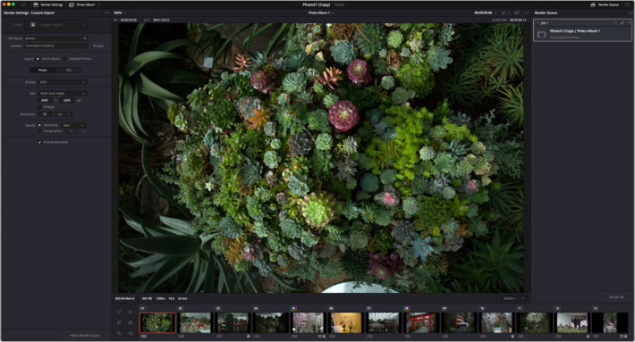
The Deliver page in Photo Album mode
To export photos from the Deliver page:
Select your File Naming, Location and Image Format in the Render Settings.
Select to either export the Entire Album or Selected Photos from the Album.
Press the Add to Render Queue button. You can change any of the export settings and then press Add to Render Queue again to export multiple output formats.
In the Render Queue press Render All to start processing your images.
Render Settings
File Name: Type in the base name of the rendered photo or photos. Pressing the + icon lets you choose common metadata types to add to the file name that automatically populate based on each photo. By default the exported file will use this name, and then a numbered suffix to ensure each shot has a unique file name.
Location: The file location where you want your photos to be saved. Click on the Browse button to open a file system requestor to choose it.
Export: Choose either Entire Album to export all photos in the album, or Selected Photos to export only the photos you’ve selected in the Album at the bottom of the Deliver page.
Photo
These settings let you choose parameters for the exported photo format. Not all formats will have all of these parameters.
Format: Choose the photo format you wish to export to. Choices include: HEIF, JPEG, PNG and TIFF.
Bit Depth: Choose the bit depth for the exported photo.
Include Alpha Channel: If your format supports an alpha channel, check this box to enable it to provide transparency information.
Size: Choose the method by which you want to size your photo.
Original: This method exports your photo exactly to it’s original dimensions.
Width and Height: This method lets you set a exact width and height in pixels for your photo export.
Short Side: This method lets you set an exact pixel value for the short side of the image (generally height), and will automatically adjust the long side based on aspect ratio.
Long Side: This method lets you set an exact pixel value for the long side of the image (generally length), and will automatically adjust the short side based on aspect ratio.
Percentage: This method lets you choose a percentage value for reducing the size of your image. Values run from 25% to 100%.
Megapixels: This method lets you choose to resize your image based on Megapixels values.
Enlarge: Check this box if your desired resolution is higher than your original resolution.
Resolution: Enter the desired resolution of the image here, in either Pixels per Inch (ppi), or Pixels per Centimeter (ppcm).
Compression: If your format supports image compression, enter your desired values here.
Include Metadata: Check this box to include metadata like location data, lens values, etc. in the exported photo.
File
These settings let you choose how the file naming of the exported photos is handled.
File Name Uses: Choose either Custom Name to create your own naming structure, or Timeline name to use the timeline’s name and a numerical suffix instead.
Custom Name: Enter text here to define the custom name, you can also include metadata variables that update with each photo, by first typing in “%” then choosing the metadata field from the dropdown list.
File Suffix: Enter text here that appears as a suffix to the custom name chosen above.
Use X Digits in the File Name: Set this number to choose how many decimal places the file numbering system uses in the file name. For example 3 digits will use numbers from 1-999, while 8 digits will use numbers from 1-99,999,999.
Photo Editing Example
The combination of having a still image editor in combination with DaVinci Resolve’s extensive film and video editing tools makes a whole new range of creative and practical photo effects possible.
For example, let’s take a standard phone camera snapshot, and make it look like it was shot on 35mm motion picture film instead.
First we will use the Photo Inspector to make standard exposure, and color balance adjustments to the image.
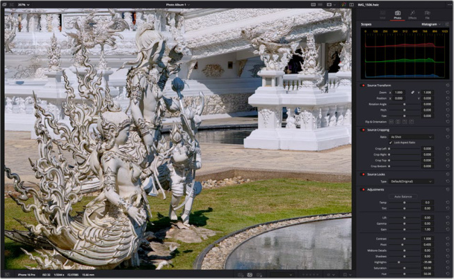
The original camera phone image
In this phone camera image the subject of the statues is hard to differentiate from the background. Having been shot with a tiny phone camera lens means that everything, including the background is in sharp focus, which tends to blend together and obscures the subject statue.
To fix this, we will drag DaVinci Resolve’s new CineFocus effect on top of the image in the album to create a new virtual lens to view this image through. We will create a lens that has a larger aperture, shallower depth of field characteristics and nicer bokeh.
CineFocus first analyzes the photo to create a new Depth Map of perceived distances inside the 2D image.
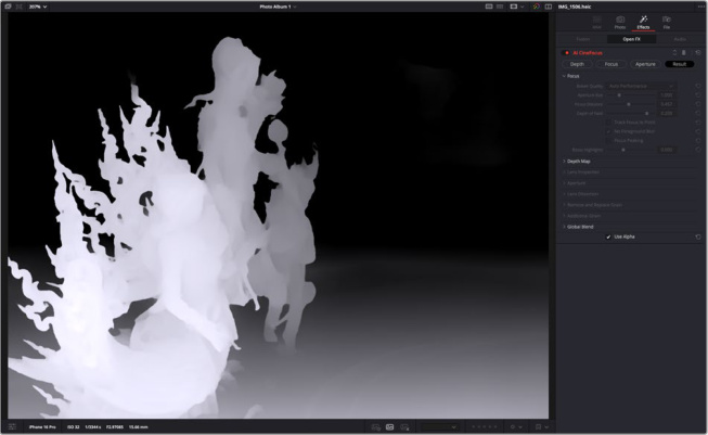
The CineFocus Depth Map analyzing which parts of the image are in the foreground (brighter) and which are in the backgroud.
Then using the Focus mode, we can set the exact aperture, and depth of field settings we want to isolate the foreground statues, while pushing everything in the background out of focus.
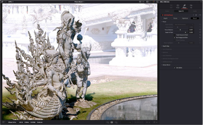
The CineFocus Focus mode lets you set a new focus distance and depth of field (color images) vs out of focus areas (white).
Then we can tweak the exact lens parameters as much, or as little as we want. From just a basic virtual lens, to an 11 bladed, anamorphic lens with a little chromatic aberration, and a slightly off center lens curvature. In this example we’ll just keep the lens parameters as the default.
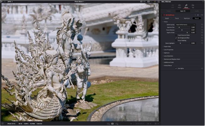
The CineFocus image, notice how the background is now effectively blurred behind the statues. The blur also increases gradually with distance, which is more realistic than simply masking an area and blurring it.
Now that the image looks like it was shot on a much more cinematic lens, we will want to complete the effect by making it look like it was also shot on 35mm motion picture film, instead of a tiny CMOS sensor. To do so, we will also drag the Film Look Creator effect on top of the image in the Photo Album. We now have two effects working on the same image in tandem.
The Film Look Creator is another deep effect, that lets you adjust film parameters like halation, grain, bloom, vignetting etc. But for this example, we will just apply the Default 35mm film preset, to add a film like color profile, and the correct size grain pattern.
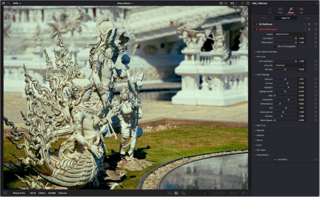
The finished image, with the Film Look Creator applied
The final image result now clearly differentiates the statues from the background, and places a nice filmic look over the entire frame.
Keyboard Shortcuts
Like all other pages in DaVinci Resolve, the Photo Page has it’s own set of keyboard shortcuts to make working more efficient.
| Function | Keyboard Shortcut |
|---|---|
| Image Capture | C |
| Capture Panel or Capture Live View must be active | |
| Star Rating | Numbers 1-5 assign star rating |
| Works in both Photo Album and Media Pool | 0 removes all stars |
| Tag Clip | S = Good Take<br>X = Rejected Take<br>Pressing S or X again will clear the tag |
| Rotate and Flip | Rotate Left: Command - [<br>Rotate Right: Command - ]<br>Flip Horizontal: Shift - [<br>Flip Vertical: Shift - ] |
| Reset and Clear | Reset Photo: Command-R |
| The Inspector must be in focus | Remove All Photo Effects: Shift-R<br>Remove and Reset All: Command-Shift-R |
Native RAW Support for Major Camera Formats
As of this beta, DaVinci Resolve supports the following RAW camera formats:
Canon CR3
Fujifilm RAF
Apple ProRAW
Nikon NEF
Sony ARW
Photo Multiuser Collaboration and Blackmagic Cloud Syncing
The Photo page can also take advantage of DaVinci Resolves extensive Multiuser collaboration and Blackmagic Cloud tools. For example, using Capture Live View in a collaboration project, lets another user view the video feed online in another location. You can also sync and store photos in a Blackmagic Cloud Folder, allowing multiple users around the world access to your photo edits, and the ability to make changes collaboratively.
Support for DaVinci Color Control Toolset and Grading Panels
The Photo Page supports the use of DaVinci Resolve color control panels, for dedicated tactile control over common image editing settings. In addition, Photo Albums can be used directly in the Color Page, which gives you access to DaVinci Resolve’s world class color grading toolset.
Photos Support for DaVinci Resolve’s Native AI Toolset
Several of DaVinci Resolve’s AI tools, like IntelliSearch, and Motion Deblur can be used on images in the Photo page.
GPU Accelerated Batch Exports and Conversions
Photo exports from both Quick Export and the Deliver Page are GPU accelerated.
Global Reduced Resolution Control
Photo uses the native resolution of your photos, and some camera’s photo formats can be exceedingly large in megapixels and resolution. As a result, native processing can sometimes slow down the computer unacceptably.
The Photo page uses a reduced preview resolution in the viewer to keep performance snappy. You can set the parameters of this setting at Playback > Photo Album Preview Resolution.
The options are:
Auto (default): Will downscale any photo that is over 4k in resolution down to 4k size for preview.
Full: Forces Photo to use the full sized resolution of the image preview, regardless of performance issues.
Half: Reduces the photo resolution by half the size for image preview.
Quarter: Reduces the photo resolution to one quarter the size for image preview.
NOTE: This setting is for previewing the working image only, rest assured on export DaVinci Resolve will always use the original full sized image for final output.
AI Tools
AI IntelliSearch
DaVinci Resolve 21 features a new powerful media organizational tool called IntelliSearch. IntelliSearch uses AI technology to provide a comprehensive, near instant media search for people and objects. The benefits for increased efficiency in finding exactly the media you need are real and immediate. For all those times when you thought “where was that clip of …?” now you can just ask DaVinci Resolve and it will find it for you.
Setting up IntelliSearch
As an AI based operation, IntelliSearch requires the download of an AI model from the Extras Download Manager. Once installed, you then need to analyze the media in your media pool, before using IntelliSearch from the search bar in the Media Pool.
Downloading the IntelliSearch Models
You can download the IntelliSearch models from DaVinci Resolve > Extras Download Manager. There are two models one for the Faster Mode, and one for the Better Mode. You can download one, or both, but your modes will be limited to the packages you have installed.
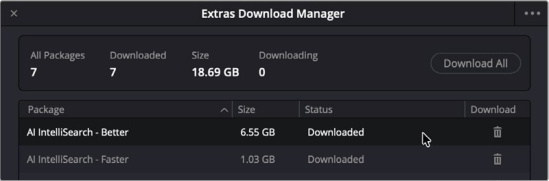
IntelliSearch AI model packages for download
Selecting the IntelliSearch Mode
Initially you will need to decide whether you want IntelliSearch to operate in Faster or Better mode. The tradeoff is processing time and the size of the model download. Both models are equally fast once the analysis is complete. Better can take significantly longer to analyze your clips, but you will get more accurate results. You can initially start with a Faster analysis and then run a Better mode later when your workstation has more downtime.
You can choose between Faster and Better in the Media Pool three-dot option menu, under IntelliSearch Mode.
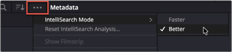
Choose Faster or Better mode for IntelliSearch
Analyzing Media in IntelliSearch
Once your model is selected, you will need to run the IntelliSearch analysis on your Media Pool clips, from the AI Clip Analysis tool. This tool provides a single location to selectively apply different AI analysis models on the clips in your Media Pool for a variety of AI driven features in DaVinci Resolve. By default the tool analyzes all clips in the Media Pool, but using the drop down menu to the right, you can have it analyze only the selected clips instead.
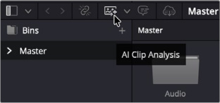
The AI Clip Analysis Icon in the Media Pool
To start the IntelliSearch Analysis, make sure the toggle switch is on next to Analyze for IntelliSearch. There is also an optional checkbox called Identify Faces, that when enabled will let IntelliSearch recognize individual humans. This lets you add their names as search criteria in the Manage Faces window in the IntelliSearch interface.
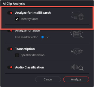
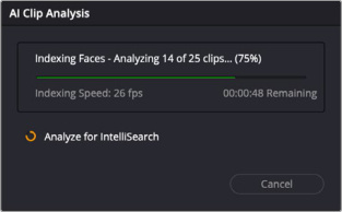
(Left) Make sure the toggle next to Analyze for IntelliSearch is on, (Right) The AI Clip Analysis progress bar
Then simply click the Analyze button and wait for your computer to finish the analysis. A progress window will appear letting you know approximately when the process will complete.
When complete, clips that have been analyzed will have the AI Analysis icon in their thumbnail, so you can know in a glance which clips have already been processed.
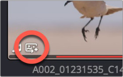
This icon appears after a clip
has been analyzed for IntelliSearch
Using IntelliSearch
IntelliSearch is accessed simply by clicking on the search icon (magnifying glass) in the Media Pool. It exposes a search bar and its surrounding toolset.

The IntelliSearch toolbar

Search Parameters: Choose what kind of search analysis to apply to your search terms.
Search All: Returns results from all types of AI analysis and entered metadata.
Search Visual Only: Returns results from the image analysis only. The Visual search allows you to search for objects and other contents in the scene.
Search Transcript Only: Returns results from the audio transcript only. The Transcription search limits search to transcribed audio, useful if you are looking for exact phrases.
Metadata Search: Returns results from any or all of the metadata fields. The Metadata search can be used to filter by keywords and other metadata (including custom metadata) and clip properties. This mode also gives you a dropdown menu to search all fields, or filter by file name, timecode and other metadata fields.


Search Field: Type in what you want to find here, it can be almost anything: an object, a person, a color, a camera number or even a line of dialog.
Add as SmartBin: Pressing this icon will open the Create Smart Bin tool, with the parameters you’ve chosen already added to the Smart Bin criteria. This lets you create a persistent Smart Bin of your search results.
Show Face Gallery: Displays a thumbnail view of every human face that was detected. Click on a thumbnail to view all shots that feature that human, or limit a search result to that human.
Manage Faces: Opens the Manage Faces tool, that lets you name and curate the various faces detected.

Search In: Lets you choose where to search,
All Bins: Searches all bins in the project.
Selected Bins: Searches only bins that have been selected.

Display: Choose how the results are displayed (for Search All, Visual only and Transcript only).
Full Clips: Returns the entire clip as a match, with a yellow line marking the duration that the search term is relevant for. Hover over the thumbnail and Press “X” to mark an in-out range based on the yellow line.
Segments: Returns just the matching duration that the search term is relevant for, effectively making it a subclip.
Face Gallery
Clicking on the Show Face Gallery icon in the IntelliSearch bar opens a thumbnail view of each human face detected in your clips. Clicking on a face will limit the search results to just that human. For example, you can click on a face named “Chloe”, as a face thumbnail, then type “red dress” in the search bar. The search results will return only images of Chloe wearing a red dress, and not the other actresses.
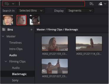
The Face Gallery, with the woman’s face selected, shows only clips she is in by default.
If you want to attach a name to the face you can go to the Manage Faces tool. Here you can add names to the faces by clicking underneath the face thumbnail, and typing the name into the field. This name is now metadata attached to that face under the People field.
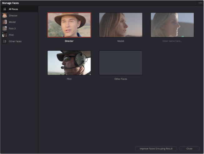
The Manage Faces tool, type a name under the thumbnail to assign it to a face.
If Face Detection made an error, you can also fix that in the Manage Faces tool. There is an automated process that works when you press the Improve Faces Grouping Result button, that will ask you to confirm who it thinks that person is. Also you can manually assign a face just by right clicking on the thumbnail and selecting “Not XXX”, and reassigning it to another face in the dropdown menu.
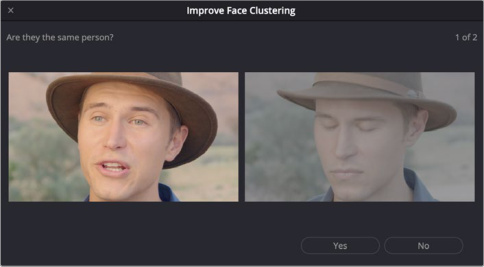
The Improve Faces Grouping Result tool, provides an automated yes / no interface to confirm faces.
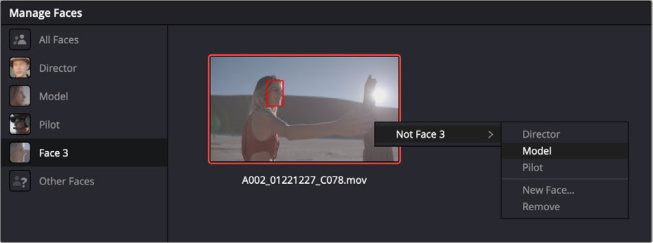
Right-clicking on a thumbnail lets you reassign the face manually.
AI Speech Generator
Speech Generator generates high quality spoken word output from written text, letting you create your own natural sounding VO or narrations for your projects with different voices and performances that you can tailor to your edit.
Timeline > AI Tools > Speech Generator
Downloading the Speech Generator Model
As an AI based tool, you will need to download the Speech Generator Model before use. You can download the Speech Generator model from DaVinci Resolve > Extras Download Manager.
Using AI Speech Generator
Launch the AI Speech Generator by going to Timeline > AI Tools > Speech Generator.
Next type in the text you want to generate in the Text Input field. Speech Generator does best with shorter sentences or paragraphs. If the text you input is too long, the generated voice can start to drift into strange territory after a while. So keep it brief, or if you have a large amount of text, break it into smaller pieces.
Then choose the Voice Model you want to read your text. There are four built in voices that are licensed for use, or you can also create your own custom voice as described below. You can modulate the voice by adjusting the parameters in the settings section.
Finally you can set the generated audio clip’s file name, and decide which audio track to insert the clip into.
When you press the Generate button, the Speech Generator will process and create a new audio clip based on your input, and put it in your Media Pool.
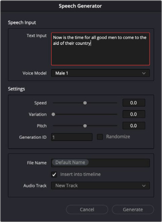
The Speech Generator tool
- Speech Input: This section inputs the text and decides which voice you want it to read in.
Text Input: Type in the text you want the Speech Generator to read here. Shorter sentences and paragraphs are better. Punctuation does affect the timing of the reading. Periods (full stops) are longer pauses, and commas shorter. Carriage returns may make a pause longer coming after a period.
Voice Model: Choose a voice model to read your text from the dropdown list. Selecting Custom will open a file requester to load an audio file with the voice you wish to use (see Creating a Custom Voice below).
- Settings: These settings control the modulation and performance of the voice.
Speed: Adjusts the speed of the reading.
Variation: Controls variation of the reading prosody (the rhythm and intonation of speech) and emotion with 0 being closest to prosody of the reference voice source.
Pitch: Controls how high or low the voice is. Positive values are higher pitched, and negative values are lower.
Generation ID: You can think of this number like a performance or take. Each number represents a different reading with varying prosody. Choosing the exact same number will give you the exact same performance, so this can be useful when you want to try other variations but keep the same prosody including emotional emphasis.
Randomize: Check this box to use a random number for the Generation ID.
File Name: The name of the new Speech Generator audio file. A default name is supplied and a numerical suffix is automatically added. You can enter your own name instead for the start of the string. Speech Generator audio files are stored in the DaVinci Resolve Media location you’ve set under their project name.
Insert into Timeline: Checking this box will automatically insert the reading at the playhead position in your timeline.
Audio Track: Choose which audio track in your timeline the reading will be inserted into.
Creating a Custom Voice for the Speech Generator
You can easily create a custom voice for use in the Speech Generator. All you need is an audio file of the person talking for about twenty seconds, that’s been recorded in a clean and high fidelity signal. Then simply load that file into the Speech Generator using the Custom setting in the Voice Model dropdown menu.
Tips for getting the best voice sample:
The recording only needs to be 10-20 seconds long. In fact, longer recordings are truncated to the first 20 seconds for Speech Generator analysis.
Make sure the voice recording is clean, with good levels and low noise.
Try to keep your spacing even, no long gaps, or extremes in volume and emotion if you want an even result.
If you’re at a loss what to record, try reading the “Harvard Sentences” out loud for twenty seconds or so. They are designed to be phonetically balanced for the frequency of the English language.
Experiment to see what works.
IMPORTANT: Ensure you get permission for using a real person’s voice and are fairly compensating the creative voice talent!
Speech Generator vs. Voice Convert
While similar in overall effect, the input driving the two AI speech tools is very different. Speech Generator creates a new audio file and performance from written text, while Voice Convert uses an existing audio file and tries to match the tonality and performance of that exact clip, just using a different voice.
In addition, Speech Generator’s voices can be generated using only a short snippet of audio, so it can be used quickly, while Voice Convert requires a longer source file and analysis time to build a voice model.
AI CineFocus
CineFocus allows you to create your own custom virtual lens that emulates realistic defocus and bokeh effects. It makes phone camera footage look like it was shot with a real cinematic lens or can be used to bring additional creative control in post-production to professionally shot footage from any camera.
The comprehensive lens build toolset is coupled with an AI generated Depth Map to create a working depth model from a 2D image, and then wrapped around an easy to use graphical interface on the viewer.
Using the Open FX overlay in the viewer presents a split-prism icon as your pointer. Assuming your footage was all sharply in focus, like from a phone camera, simply clicking a region in the viewer will “focus” the lens on that subject, while the rest of the CineFocus parameters will determine what, where, and how the out of focus regions will be generated.
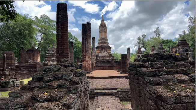
The original phone footage, with everything in sharp detail.
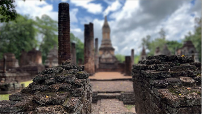
The same image, with the focal point changed to the wall.
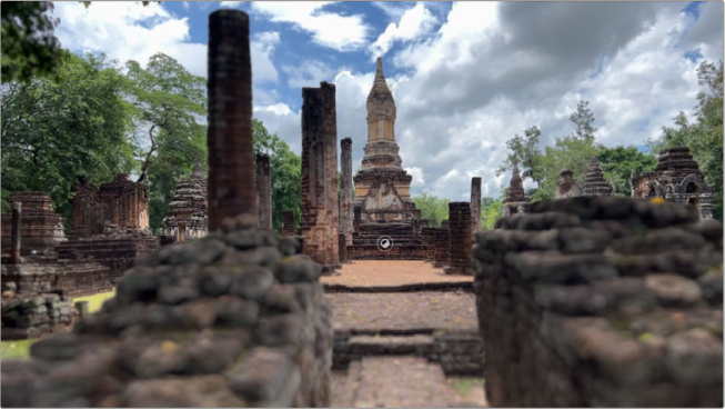
The same image but with the focal point changed to the temple
The effect is setup to work from left to right using the four mode tabs at the top of the inspector.
Depth Mode
Click this button to show the depth map view, and activate the Depth Map toolset. Brighter objects are “closer” to the camera, grey areas are in the mid-field, and darker areas are in the distance. This view shows what the AI thinks is closer or further away from the camera, and is modifiable with the Depth Map controls below.
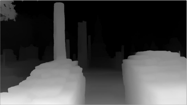
The CineFocus Depth Map view. Brighter areas are “closer” in depth.
Focus Mode
Click this button to show the focus mode view and activate the focus controls. Colored areas are in focus, while grayer areas will be defocused. With the OpenFX overlay on, you can click to focus an area in the viewer, you can also click and drag the split prism icon to select a range of focus. The CineFocus controls will then work on the defocused (gray) areas of the image.
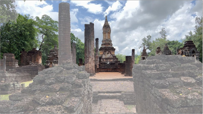
The CineFocus Focus view, greyed out areas will be out of focus. The split prism icon lets you click on areas in the viewer to focus.
Aperture Mode
Click this button to show Aperture mode. This view is a representation of the internal physics of the virtual CineFocus lens. This view lets you visually sculpt your lens properties as you adjust the sliders. At the top of the diagram it will show the light path spread from the foreground “in front” of the focal point (on the left), through the focal point (the narrow middle), to the background “behind” the focal point (on the right). Underneath the light path are Bokeh “slices” from the range above that let you see the shape and size of the Bokeh for a fixed distance.
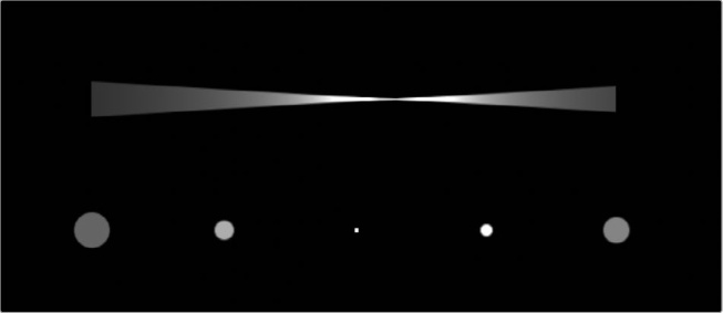
The CineFocus Aperture view. Showing the virtual lens characteristics.
Result
Click this button to see the final result of the CineFocus tool, and further adjust any parameter in the effect.
Focus
This toolset lets you change the focus parameters of the virtual lens. Using the Focus mode view above can show you the results of these tools in greater detail.
Bokeh Quality: Enhanced will adjust quality by the source resolution, it gives finer detail but can be slow at high aperture size. Better produces softer bokeh but is more efficient. “Faster” increases optimizations with frame resolution.
Aperture Size: Adjust this slider to change the virtual aperture. Higher values will add more blur to the out of focus areas of the image.
Focus Distance: Adjust this to set the focal point of the virtual lens, based on the data from the depth map. This virtual lens can not focus in units of meters or feet, instead it is a percentage value based on the Depth Map. You can keyframe and animate this value to “pull focus” from one distance to another.
Depth of Field: Depth of Field (”DoF“ in photography) is a measure of the range of depths which are considered in-focus. In CineFocus this can be artificially extended to keep a subject perfectly in focus without having to reduce the strength of the near/far defocus”.
Track Focus to Point: Check this box to make focus follow a point that you can set in the FX Overlay in the viewer. This point can be used by the FX Tracker to track focus throughout the clip.
No Foreground Blur: Check this box to remove the blur from the foreground, keeping it in focus. This makes it easier to ensure that a foreground subject stays in focus when that’s the goal, and this option can also increase performance.
Focus Peaking: Check this box to enable focus peaking lines that highlight areas in the frame that are in focus. This mimics the same function found in real cameras.
Boost Highlights: Increase the brightness levels of the highlights. It controls the balance of dark and bright regions when blurred together. This can be useful for brightening bokeh against dark backgrounds, and can generally tune the result depending on your color management
Depth Map
This toolset lets you adjust the Depth Map, showing a simulated depth inside a 2D image. Using the Depth mode view above can show you the results of these tools in greater detail.
Source: Choose Internal for creating a Depth Map inside the CineFocus tool, or From Alpha Input if you’ve created a Depth Map in another node.
Quality: Choose whether to prioritize speed (Faster), or quality (Better).
Invert: Check this box to invert the Depth Map, reversing what is considered near or far in the image.
Adjust Map Levels: Check this box to fine tune the Depth Map, and activate the toolset below. Far Limit: Adjusts the black levels of the Depth Map, determining the limit for how “far away” the map will cover.
Near Limit: Adjusts the white levels of the Depth Map, determining the limit for how “close up” the map will cover.
Gamma: Adjusts the gamma curve of the Depth Map, letting you decide the relative “distances” between near and far objects.
- Post Processing: Check this box to make adjustments to the black and white Depth Map, and activate the toolset below.
Post Filter: Adjust this slider to smooth the Depth Map along the image contours.
Contract / Expand: Adjust this slider to contract or expand the white foreground areas of the Depth Map.
Blur: Adjust this slider to soften the Depth Map, which can help if it contains jagged edges to be smoothed over, but can cause artifacts at image object edges. This option is only recommended for repair of a difficult depth map
Separate Layers: Adjust this slider to improve the depth edges, where one object is in front of the other. This can help separate distances with depth maps that are not completely sharp. When using an external Depth Map, make sure this is set to 0.0.
Lens Properties
This toolset lets you modify the virtual lens to be less than perfect. This provides a more realistic result, and makes it easier to match the characteristics of a real lens.
- Chromatic Aberration: Check this box to simulate Chromatic Aberration, the fact that different frequencies of light focus at different depths.
Strength: Adjusts the strength of the color separation.
Phase: Adjusts the relative bending of the different frequencies, depending on the lens optics.
- Spherical Aberration: Check this box to simulate Spherical Aberration, the fact that large apertures can make the focal point spread across a range of different depths. Lens Model: Choose the lens construction type to simulate.
Strength: Adjusts the light dispersion.
Aperture
This toolset lets you adjust the Aperture characteristics of the virtual lens. Using the Aperture mode view above can show you the results of these tools in greater detail
Shaped Bokeh: Check this box to adjust the Bokeh of the virtual lens and access the toolset below. Unchecking this box will result in perfectly circular Bokeh.
Number of Blades: Adjust the slider to set the number of blades in the aperture of the virtual lens. Each blade will change the shape of the Bokeh accordingly.
Rotation: Adjust to rotate the aperture shape left or right.
Curvature: Adjusts the curvature of the aperture blades.
Pinwheel: Adjusts how much of the blade tips are visible. Pinwheel refers to a ratchet-like shape in the bokeh (the out-of-focus highlights) visible with some lenses at wide-aperture, that resembles the shape of a pinwheel fan.
- Anamorphic Lens: Check this box to set the Bokeh to have an anamorphic shape.
Anamorphism: Adjust this slider to set the amount of the anamorphic stretch.
Lens Distortion
This toolset lets you adjust the distortion characteristics of the virtual lens. This replicates the fact that lenses create Bokeh at different sizes depending on their distance from the lens center.
- Curved Lens: Check this box to add artificial curvature to the lens, and activate the toolset below.
Curvature: Adjust the strength of the distortion around the edges of the frame.
Lateral Aberration: Adjusts the color distortions in the blurring at the edges of the frame.
Phase: Adjusts the relative spread of the different colors, depending on the lens optics.
Foreground Edge Overlap
This toolset lets you adjust how the foreground edge overlap is blended into the rest of the image. If the foreground does not overlap, these tools will have no effect.
In a real optical system, objects close to the lens get “blurred-out” and are transparent. For example if you hold the tip of a pen pointing up, close to your eye, you can see through it completely. These physics don’t apply to 2D video, so these tools provide a workaround that simulates that phenomenon.
Overlap Preview: Check this box to see where the foreground edge overlaps the rest of the image.
Overlap Boost: Adjust this slider to make the overlapping foreground denser to help hide the transition edge. You can only use this tool if Automatic Edge Handling is deselected.
Automatic Edge Handling: Check this box to automatically create nice defocused overlaps, at the cost of some background detail in the overlapping regions. Using this tool disables Overlap Boost.
Remove and Replace Grain
In real footage, film grain and video noise are independent of depth of field, spread uniformly across the image. When the CineFocus tool blurs the background, it blurs out the grain in these regions but also has partially-blurred grain through slightly-blurred regions (depending on the blur and the grain), which is later difficult to deal with. With this toolset you can initially remove grain in the image to defocus the background more accurately, then add it back in again after the defocus for the effect of having an image which had defocus by depth before it was captured to film
Remove Grain: Checking this box, activates the Remove and Replace toolset.
Grain Detection: Choose the method that analyses and removes the grain. Enhanced Spatial, or AI Ultra Noise Reduction.
Estimate Best Thresholds: If AI Ultra Noise Reduction is chosen above, you can click this button to let the AI determine the grain vs detail threshold.
Split Luma Chroma Thresholds: Check this box to set separate grain thresholds for Luma and Chroma signals.
Threshold: Adjust this slider to set the threshold between what is grain and what is edge detail.
Preview Grain: Check this box to see a preview of the just the grain in the viewer, making it easier to see the effect of the parameters in this toolset.
Replace Grain After Defocus: Check this box to add all the grain you just removed, back into the defocused areas after processing.
Grain Replacement: Lets you determine just how much of the grain to add back in.
Additional Grain
This toolset lets you add a grain layer over the entire image.
Add Grain: Check this box to activate this toolset.
Strength: Adjust this slider to determine how much grain should be added to the image.
Size: Adjust this slider to determine the size of the grain particles.
Softness: Adjust this slider to determine how blurry or sharp the grain particles are.
Saturation: Adjust this slider to determine how colorful the grain particles are.
AI Face Age Transformer
The Face Age Transformer lets you artificially age or de-age the face of your subject. As an AI tool, the Face Age Transformer will automatically add or subtract wrinkles, skin tautness, and other aging related attributes to your subject, and track them along consistently with their head movements and position.
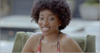
The original footage
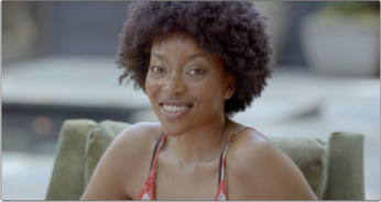
The model aged by 30 years
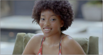
The model de-aged by 20 years
Currently Face Age Transformer only ages the face itself, It does not guarantee the neck, ears, or hair color of the subject will be affected. Occasionally, regions other than the face may be affected. In such cases, the user might want to apply a separate tracking mask to the face to isolate the effect to only the face. Intentionally dirty or shadowed faces can also throw off the AI analysis.
The Face Age Transformer is a two part operation. The first part is identifying and tracking the face you want to age, and the second part is adjusting the amount of aging you want to apply.
Face Location and Tracking
These tools identify the face you want to age and track it throughout the clip.
- Face Location: Informs the tool where to look for the face to age.
Detected: Find the face by tracking it using the effect’s internal tracking tools.
From Input Alpha: Find the face by using an alpha channel input from another node. There is an option to preview the alpha channel if needed.
Detect Faces in Frame: Click this button to have the tool find any recognizable faces in the frame with a bounding box. If multiple faces are found, you can choose the one you want to age by clicking on the box. The active face box will turn green, while any other faces not affected will be in red.
Track Reverse: Tracks the face box backwards from the current position to the beginning of the clip.
Track Reverse 1 Frame: Tracks the face box backwards one frame from the current position.
Find in Frame: Snaps the face box to a face in the current frame, useful if the tracking was interrupted.
Track Forward then Reverse: Tracks the face box backwards to the beginning of the clip, then forwards to the end, ensuring it’s been tracked along the entire length of the clip.
Track Forward: Tracks the face box forwards from the current position to the end of the clip.
Track Forward 1 Frame: Tracks the face box forwards one frame from the current position.
Show Overlay: Check this box to toggle the face box overlay on or off in the viewer.
Manual Adjustments: A keyframable attribute that lets you override the tracking data for the face position.
Age Shift
These tools let you guide the AI aging parameters. All values are in human years.
Subject’s Age: Adjust this slider to the perceived age of the subject in the frame.
Age Offset: Adjust this slider to the desired amount of years to add or remove from the subject. The Face Age tool will automatically make the face of the subject look older or younger.
NOTE: If the Subject’s Age field has a relatively low value (e.g., 30), moving the Age Offset to lower values will stop having an effect as the model has a maximum range it can effect.
AI Face Reshaper
The Face Reshaper lets you make adjustments to the size and shape of the different elements of a subject’s face, while giving you temporally consistent results over the length of the clip. The Face Reshaper is best used minimally, with small, subtle adjustments. Humans have evolved to be especially sensitive to faces, and adjusting this toolset too aggressively will careen the results deep into the uncanny valley very quickly.
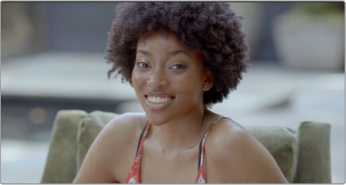
The original image
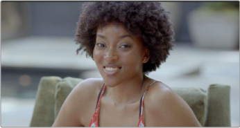
The Face Shape operation to reduce the size of her mouth.
The Face Reshaper is a two part operation. The first part is identifying and tracking the face you want to shape, and the second part is adjusting the actual shaping you want to apply.
Tracking
Detect Faces in Frame: Click this button to have the tool find any recognizable faces in the frame with a bounding box. If multiple faces are found, you can choose the one you want to reshape by clicking on the box. The active face box will turn green, while any other faces not affected will be in red.
Track Reverse: Tracks the face box backwards from the current position to the beginning of the clip.
Track Reverse 1 Frame: Tracks the face box backwards one frame from the current position.
Find in Frame: Snaps the face box to a face in the current frame, useful if the tracking was interrupted.
Track Forward then Reverse: Tracks the face box backwards to the beginning of the clip, then forwards to the end, ensuring it’s been tracked along the entire length of the clip.
Track Forward: Tracks the face box forwards from the current position to the end of the clip.
Track Forward 1 Frame: Tracks the face box forwards one frame from the current position.
Show Overlay: Check this box to toggle the face box overlay on or off in the viewer.
Face Location
Manual Adjustments: A keyframable attribute that lets you override the tracking data for the face position.
Interpolate: In case there are tracking errors, you can set your own start and end points of the face movement and have the tool automatically interpolate the intervening frames. To set the start frame, navigate to a frame and then check this box. To set the end frame, navigate to a frame, drag the face box to the face’s position and then uncheck this box.
Face Shape
Adjust Face: Checking this box enables or disables the Face Shape toolset.
Size : Shrinks or grows the overall size of the face.
Width : Shrinks or grows the width of the face.
Length : Shrinks or grows the length of the face.
Cheek Position : Positions the cheek bones higher or lower in the face.
Chin : Shrinks or grows the size of the chin.
Jaw : Shrinks or grows the size of the jaw.
Forehead : Shrinks or grows the size of the forehead.
Eyes
Adjust Eyes Separately: Checking this box splits the toolset into left and right eyes independently.
Adjust Eyes: Checking this box enables or disables the Eyes toolset.
Size: Shrinks or grows the overall size of the eyes.
Height: Shrinks or grows how open the eyes are.
Separation: Adjusts the distance between the eyes.
Position: Adjusts the position of the eyes up or down in the face.
Angle: Adjusts the tilt angle of the eyes.
Eyebag: Adjusts the position of the bags under the eyes.
Nose
Adjust Nose: Checking this box enables or disables the Nose toolset.
Size: Shrinks or grows the overall size of the nose.
Width: Shrinks or grows the width of the nose.
Height: Shrinks or grows the height of the nose vertically in the face, not how far it protrudes from the face.
Mouth
Adjust Mouth: Checking this box enables or disables the Mouth toolset.
Size: Shrinks or grows the overall size of the mouth.
Position: Adjusts the position of the mouth up or down in the face.
Width: Adjusts the width of the mouth.
Smile: Adjusts the angle of the mouth to produce a smile or a frown.
Eyebrows
Adjust Eyebrows Separately: Checking this box enables a separate left / right Eyebrow toolset.
Adjust Eyebrows: Checking this box enables or disables the Eyebrow toolset.
Position: Moves the brow up or down vertically in the face.
Separation: Adjusts the distance between the eyebrows.
Thickness: Shrinks or grows the thickness of the eyebrows.
Tilt : Adjusts the angle of the eyebrows.
AI Blemish Removal
Blemish Removal is an AI powered tool for removal of facial and skin blemishes, like acne, scars, and other imperfections. As video cameras increase in resolution, close-ups of faces can magnify even the tiniest of skin issues into gigantic distractions. This is a very simple skin-smoothing tool that will make your actors happy.
- Strength: Adjusts the amount of Blemish Removal.
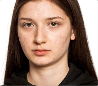
The original footage
After Blemish Removal
NOTE: Blemish Removal can get confused by intentionally dirty faces (like a firefighter with soot on their face).
AI Slate Finder and AI Slate ID
Slate Finder uses AI to automatically detects slates (clapper boards) and mark their positions on your clips including the clapper close point. Slate ID will read Scene, Take, Angle, Shoot Day and other information written on the slate, then offers options to populate a clip’s metadata.
As an AI based operation, Slate Finder and Slate ID first requires the download of an AI model from the Extras Download Manager.
To analyze slates, select the clip or clips with slates you want to analyze in the Media Page, then rightclick on one of them and select AI Tools > Analyze for Slate. Or toggle on Analyze for Slate in the AI Clip Analysis tool whose icon is at the top of the Media Pool.
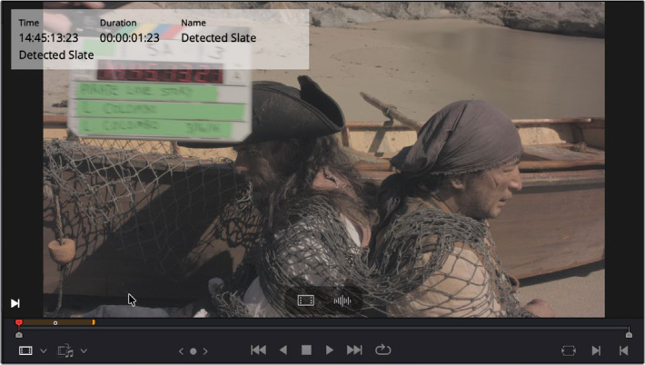
The Slate Finder has identified the frames in which the
slate appears, and marked them as a yellow duration marker.
NOTE: As of this beta, Slate Finder and Slate ID are still works in progress, all functions may not be completely available yet.
AI UltraSharpen
UltraSharpen is designed to create extremely high quality sharpening in moving video images. Since UltraSharpen is an AI tool, it selectively sharpens only where it thinks it is needed, and doesn’t apply a blanket sharpen over the whole image. In practical terms, it means that if you have a shot that’s slightly soft or out of focus UltraSharpen just may be able to rescue it. It can also intelligently improve the resolution of low resolution footage.
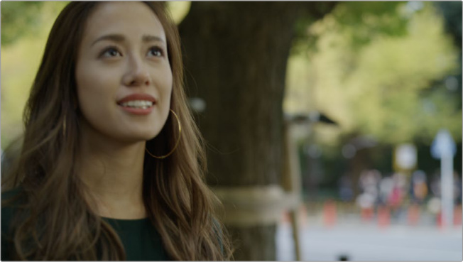
The subject in this frame is slightly out of focus
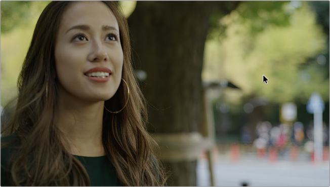
The subject with UltraSharpen, notice the increased details in the face and hair, while the background remains untouched.
It’s a very simple tool, with only one control.
Sharpen Amount: Set the amount of sharpening you want to apply to the image.
AI Motion DeBlur
Motion DeBlur is an AI tool designed specifically for the removal of common motion blur artifacts, including softness from a clip. This will result in crisper, more in-focus images from footage shot at slow shutter speeds.
As an AI based operation, Motion DeBlur first requires the download of an AI model from the Extras Download Manager.
Motion DeBlur renders new media clips to your workstation, and adds them to your Media Pool. It does not replace the original footage.
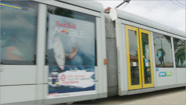
The original footage with motion blur.
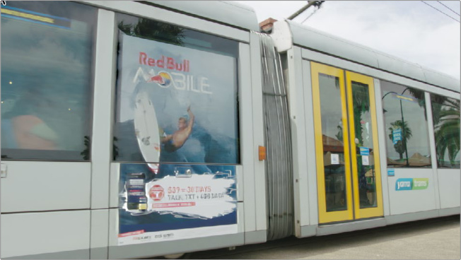
The crisper footage after the Motion DeBlur operation.
To apply Motion DeBlur to a clip:
1 Select one or more clips in the media pool.
2 Right-click on one of them and select AI Tools > Remove Motion Blur
3 Adjust file name, codec, and mode from the Remove Motion Blur dialog
4 Click Render.
NOTE: Motion DeBlur is a very resource intensive operation that can take up to 60 seconds per second of footage to analyze.
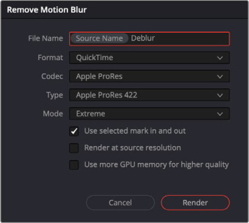
The Remove Motion Blur Dialog
The Remove Motion Blur dialog lets you choose the following parameters:
File Name: Lets you choose the file name for the new DeBlurred media clip.
Format: Select the video format for the new DeBlurred media clip.
Codec: Select the video codec for the new DeBlurred media clip.
Type: Select the video codec type for the new DeBlurred media clip.
Mode: Choose the amount of blur to remove from the clip, either standard or extreme depending on the amount of motion blur you start with.
User selected mark in and out: Checking this box renders only the media between the set In and Out points of the clip, in order to keep render times manageable. Unchecking this box renders the entire clip.
Render at source resolution: Checking this box renders the new DeBlurred media clip at its source resolution. Unchecking this box renders it at the timeline resolution.
Use more GPU memory for higher quality: Checking this box increases the amount of GPU ram used in the operation, for higher quality results.
Some tips for better results from Motion DeBlur:
Moderate motion blur caused by slow camera panning is generally handled well by the model.
Videos with noticeable camera shake can also work well, provided the main subject remains visible in every frame. In particular, footage where the subject stays near the center of the frame throughout the clip tends to perform better. Small variations in framing are acceptable and may still produce good results.
For example, recording a city scene while walking slowly or standing still with slight handheld motion can be effective.
Clips that include at least some sharp frames usually lead to stronger deblurring results. For instance, a video may contain brief blur during a step or movement, while the remaining frames stay relatively clear.
Higher frame rates can improve results in more challenging cases, although extremely difficult motion blur may still remain beyond the model’s capabilities.
Avoid very fast camera movement especially when the subject moves rapidly across the frame, such as from one corner to another within a few seconds.
Cut and Edit
Canva Affinity .af File Support
Canva Affinity .af files can now be decoded natively in the DaVinci Resolve timeline. When an Affinity file is imported to the media pool, it will be flattened and rasterized by default. This image can be used in a timeline similar to any other still image format.
Once on the timeline however, you can split the Affinity file back into its individual layers again, with each layer expanding to a new video track. If the Affinity file is composed of multiple layer levels or groups, these will initially be composited together on a single video track, but can be further split into individual layers as needed.
To split a Canva Affinity .af file on the timeline:
1 Select the .af clip on the timeline.
2 Right-Click on it and select “Split Layers in Place”
For example, this Affinity file is made up of a group of several layers, and those layers are further sub grouped into head, body, and legs.
The original layered Affinity file
Bringing the file into a Timeline, rasterizes and flattens all of the layers by default.
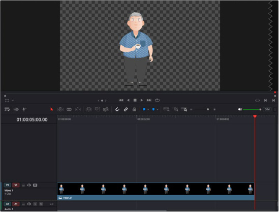
The Affinity file in a Timeline
Right-clicking on the image in the timeline and selecting “Split Layers into Place” will expand the file into its first set of layer groupings on the timeline. In this case, Head, Body, and Legs.
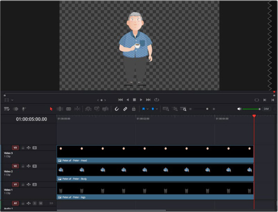
The Affinity broken up into Head Body and Legs layers
If you wish, you can further subdivide the layers into more tracks, by right-clicking on one of the layers in the timeline and once again selecting “Split Layers in Place.” Here you can see the Body group split up into its individual layers.
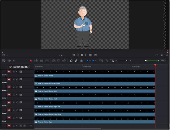
The Body layer group expanded into its component layers
From here you can then modify, animate or edit the individual layers further in DaVinci Resolve. You can also recombine layers back again by selecting them and making a compound clip.
Back in Affinity, you can continue to change and modify the image, and once those changes are saved they will automatically update inside DaVinci Resolve. However making major changes in the layer grouping and hierarchy in Affinity may not reflect correctly back into DaVinci Resolve, and in that case you should just re-import the changed .af file into the media pool again.
Enhanced Retime Keyframing Controls
The Retime parameter controls in the Keyframe Editor have been enhanced to use the same bezier easing tools as the other parameters. You can use these tools to achieve complex retime effects, like easing into a freeze frame, or smoothened non-linear speed ramps in a clip.
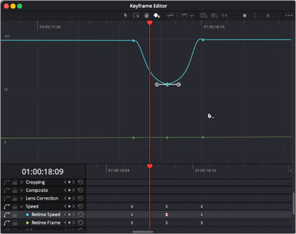
The Speed controls can now use bezier easing
to make smooth changes to the retime speed
Keyframe and Add Curves for Selected Clips
Keyframe editing now works with multi-clip selection. Whether your clips are arranged side by side or stacked vertically, you can select the clips you want to work on, enable Keyframe mode, and adjust their keyframes directly. The selected clips keyframes will show concurrently if stacked or sequentially if side by side. This lets you both save time by keyframing a sequence of clips, and give you a visual guide on how the different curves and keyframes can be compared between clips.
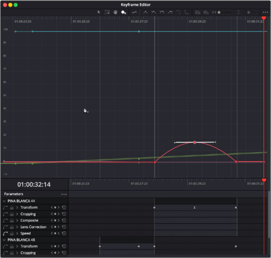
The Keyframe / Curves editor with multiple clips selected (sequentially).
New Keyframing Ease Options
For advanced keyframing there are new ease functions that you can set on individual keyframes, or change the interpretation behavior between multiple keyframes.
Step In/Out:
Step in and out let you instantly change the state of a keyframe from one to another without interpolation. For example you may want the second hand on a clock illustration to tick forward, instead of sweep forward.
To step a series of keyframes multi-select the keyframes you want to adjust and choose either Step In or Step Out icons at the top of the Keyframe Editor.
Step In will hold the value of the previous keyframe, then jumps to the next keyframe.
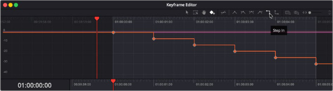
Step In applied to a group of keyframes on a curve.
Step Out will jump immediately at the keyframe, and holds that value until the next keyframe.
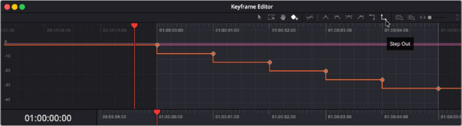
Step Out applied to a group of keyframes on a curve.
Loop:
Looping a series of keyframes lets you easily set up a repetitive motion without having to go through all the work of setting up each keyframe manually. The initial selected keyframes motion is duplicated along the entire length of the clip. For example, you may have a walking animation setup that continues automatically after the first “step” is defined.
To Loop a series of keyframes multi-select the keyframes you want to repeat and choose Loop from the Option Menu > Loop Type in the Keyframe Editor.
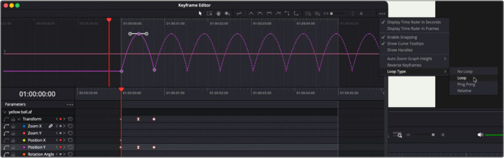
The first three keyframes are Looped along the entire length of the clip
Ping Pong:
Similar to loop Ping Pong also automatically generates a series of keyframes, but instead of repeating the sequence, Ping Pong reverses the sequence when it gets to the end, then reverses again when it arrives back at the beginning. The classic example of this is a bouncing ball.
To Ping Pong a series of keyframes multi-select the keyframes you want to repeat back and forth and choose Ping Pong from the Option Menu > Loop Type in the Keyframe Editor.
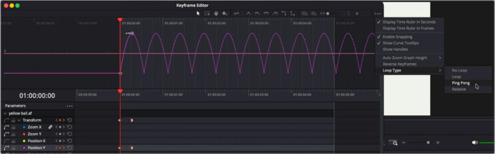
The first two keyframes are Ping Ponged back and forth along the entire length of the clip
Reverse:
Reverse is a very simple operation, taking your keyframe selection and running it backwards along the same keyframe path.
To Reverse a series of keyframes multi-select the keyframes you want to reverse and choose Reverse Keyframes from the Option Menu in the Keyframe Editor.
Shape Box:
The shape box allows you to adjust the interpolation between multiple keyframes in a consistent measured manner by bounding them in a box, that you can manipulate the edges of. Keyframes within that box will stretch and contract as you move the box’s edges.
You can select the shape box from the toolset at the top of the Keyframe Editor, then draw the box around the keyframes you want to move. Holding the Option key and moving the corners of the box let you skew the keyframes in a specific direction.
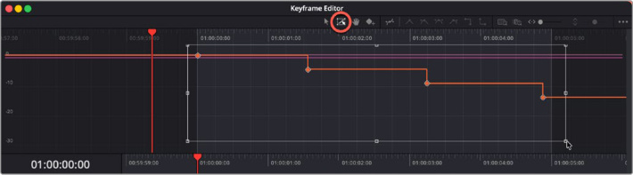
The Shape Box icon (circled red) lets you draw a bounding box around a series of keyframes to stretch or expand them.
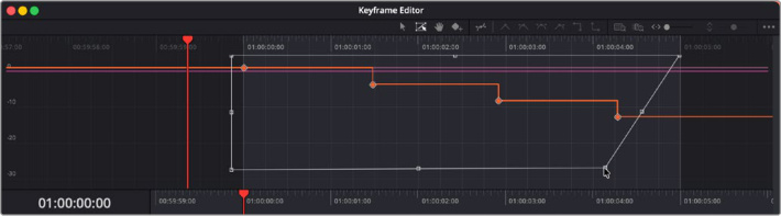
Holding the Option key and moving the corner of the box lets you skew the keyframes.
Keyframe Fusion Effects, Generators and Text Tools in the Keyframe Editor
Fusion Effects, Generators, and Text tools can be keyframed using their Fusion parameters in the Keyframe Editor. Simply select one or more Fusion titles, effects, or transitions to view these properties in the keyframe editor. Fusion based clips can have a significant number of associated parameters, so you will want to limit those to just the ones you need to keyframe using the Display Selected Parameters tool in the Keyframe Parameters 3-dot option menu.
NOTE: This only applies to Fusion effects found in the Cut and Edit pages. Normal Fusion clips and compositions will still use Fusion’s extensive keyframe editor instead.
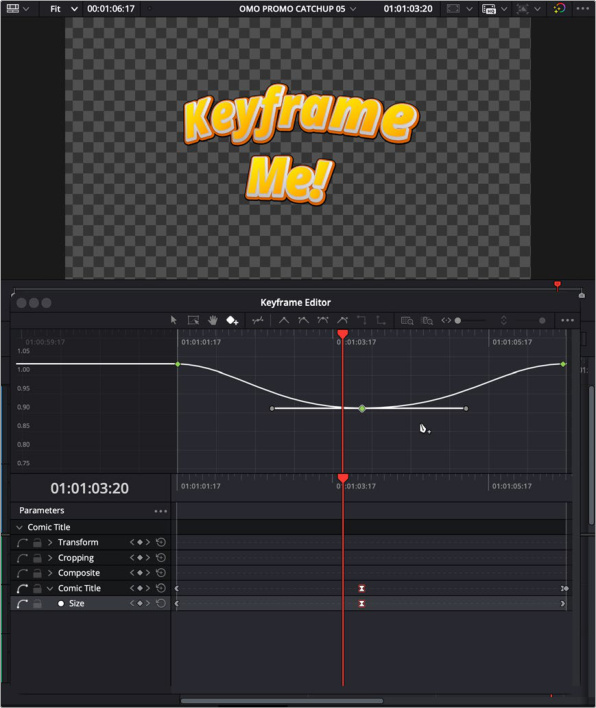
The Keyframe editor modifying a Fusion Title.
Subframe Support for Audio Keyframing and Markers
The DaVinci Resolve 21 Edit timeline includes multiple quality of life enhancements for audio workflows. Accurate subframe audio adjustments require you to be almost completely zoomed in on the timeline.
You can add and move audio keyframes with subframe, audio sample accuracy on the edit page. For easier addition of keyframes, you can press alt, press left mouse button to add the keyframe, then drag it to position and release to finalize the action.
You can also add and move markers and duration markers to start and end between frames. This applies to both clip and timeline markers.
When zoomed in, you can scrub the edit timeline in sub-frame increments with full audio feedback.
Support for OGraf HTML Graphics and Lottie Animations
DaVinci Resolve 21 adds support for OGraf (.json) and Lottie (.lottie) HTML based animation on macOS and Windows. Animation, whether it’s something you found online or created from scratch, can now be added directly to your timeline. Simply export your .json or .lottie file, then drag and drop it into your Media Pool just like any other media. You can also drop it straight into the timeline, where it will be recognized and treated like a fully rendered animation clip. The alpha background is also recognized, so transparency is maintained. You can simply drop the clip over another layer and it will composite correctly, which makes it perfect to use as a stinger or transition.
Additionally, Fusion now includes a new node called OGrafLoader. This handy tool lets you easily load your OGraf or Lottie files directly into your composition.
Font Browser for Choosing Text and Subtitle Elements
When selecting and choosing a font for text based elements, users can now choose to show an expanded Font Browser. The Font Browser expands and emphasizes the text faces making it easier to choose the perfect font.
You can launch the Font Browser by clicking on its icon near the font selection box in various tools.
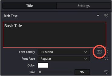
The Font Browser can be launched by clicking on its icon (circled red).
The Font Browser presents a detailed view of your installed fonts. To choose a font, simply select it in the Font Browser, then press the Select button. That font will now be loaded in the font selection field of your tool.
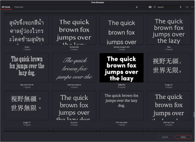
The Font Browser in Thumbnail View
When you click on a font, you are actually selecting the entire font family. If the family has multiple styles in thumbnail mode, small circular forward and back icons will appear under the font, letting you step through each font iteration. In List view there is a disclosure triangle near the font name that will show them all. There is also a star icon that can be clicked in the upper right of the font face, which will add the selected font to the Favorites tab.
With the Font Family selected, you can navigate each iteration by clicking on the left and right arrows. Clicking on the star in the upper right Favorites the font.
The Font Browser is resizable, and also has a simple toolset to help you identify the perfect font.

The Font Browser Toolbar
All Fonts: Click this tab to show all installed fonts on your machine.
Favorites: Click this tab to show only fonts that you have favorited by clicking on their star.
Scale: This slider increases or decreases the size of the font boxes.
Thumbnail View: Presents fonts in a series of square thumbnails.
List View: Presents fonts in a series of long rectangles.
Search Bar: If you know the name, or even part of the name of the font you want, you can type it in here to only return fonts with those results.
Light / Dark Mode: Choose between light or dark text with the opposite background.
Filter: Check individual classification and weight parameters to filter fonts by just those types.
Option Menu: Choose the following options:
Display Default Text: Displays “The Quick Brown Fox…” text string in the font windows.
Display User Custom Text: Allows you to enter your own text to display in the font windows.
Reset User Custom Text: Resets any custom text that has been entered.
Show Font Previews Preference
While the Font Browser will let you compare and contrast a variety of fonts with great specificity, sometimes you just want a quick look at the typefaces before you make a decision. This is where the Preview Fonts preference comes in.
On by default, Preview Fonts will display an expanded window with the font name, and then the font name again in that typeface. Selecting a font from this window will insert it into the Font Field in a variety of text tools.
You can disable this behavior if you wish by going to DaVinci Resolve > Preferences > User > UI Settings and unchecking the “Show font previews” box.
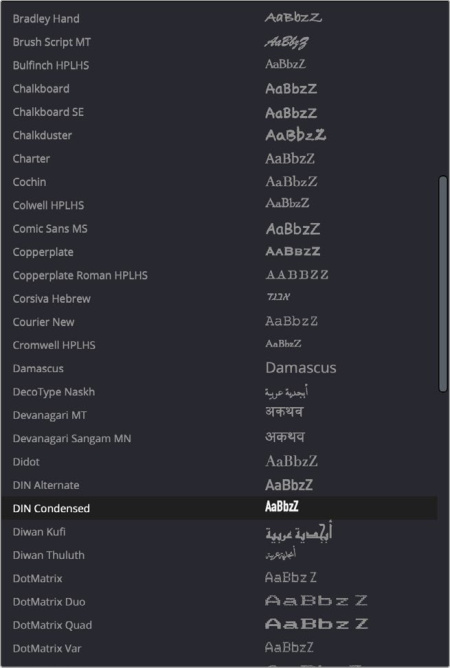
Choosing a font with the Show Font Previews preference turned on
Spell Checking for all Text Elements
As a nice quality of life improvement for the grammatically challenged, DaVinci Resolve 21 includes a multi-language text spell checker. Any spelling mistakes are highlighted red in both the viewer and inspector. Right click on a word to preview suggested replacements or ignore the word.
Misspelled words are underlined in red. Right-clicking on an underlined word gives you suggested fixes as well as an option to ignore.
There is also an associated preference set for Spell Checking in DaVinci Resolve > Preferences > User > Language and Spelling.
Spelling and Formatting Tool: Lets you modify the spell checker.
Spelling Check: Check this box to turn on or off the spell checker throughout DaVinci Resolve.
Ignore Words: Opens a text box where you can add words to the spell checker’s ignore list.
Ignore words with numbers: Will not flag a misspelled word if it includes numbers.
Ignore words with ALL CAPS: Will not flag a misspelled word if it includes all capital letters.
TIP: You can toggle off all red underlines in the viewer to ensure clean previews by selecting View > Show Spelling Errors on Viewer.
Emoji and Color Fonts for Text+ and MultiText
Emoji support is included for both Text+ and MultiText, giving you the flexibility to add expressive icons and visual accents directly within your text for more dynamic and engaging designs.
You can add emoji directly into the text fields by pressing Control-Command-Space on macOS, and Windows key-. (period) on Windows.
In addition, Text+ and MultiText features a more robust font support, with improved support for color fonts, bitmap fonts, and font styles. With supported color fonts, the Text+ inspector shows additional controls for Color Palettes under Advanced Controls, where you can select display options for the font.
Multicam Clips can Include All Audio Tracks for Each Angle
There is a new option when creating a Multicam Clip, to have all of the audio tracks from all of the various angle source clips included in the Multicam Clip. To choose this option select “All Angles” from the Multicam Audio dropdown menu in the New Multicam Clip dialog box. This means if angle A had four audio tracks, while angle B had five, all nine audio tracks would be available in the Multicam Clip.
Multicam Clips can Use Full Clip Extents on Creation and During Sync
There is a new option when creating a Multicam Clip to have all of the angles selected for the multicam clip to use their full length (extents) regardless of the length of the multicam clip. To choose this option, check “Use full clip extents” in the New Multicam Clip dialog box.
Multicam and Nested Clip Match Frame Improvements
DaVinci Resolve 21 has made additional improvements how match framing works with multicam and nested clips. When Clip > Match Frame to Source Clip is chosen, the underlying source clip for compound clips and multicams is found automatically.
Depending on UI focus, this function will work on either the source or timeline viewer, and will also exit the source timeline mode automatically if it's active.
Replay Control to Limit View to the Last 5 Minutes
There’s a new Recent Five Minute button in the Replay Viewer interface. Pressing that button opens up only the last five minutes of a growing live file in the viewer, allowing you to view, add markers etc, to only the latest five minutes of footage. This is especially useful when you’re switching a lengthy live event, and need to identify something that just happened without having to scrub through the entire clip in the viewer.
Recent Five Minute icon
Replay Editor Allows Timeline Selection from Search Dial
You can now view and select up to the last ten timelines in the Replay Editor. To do so, simply hold down the timeline button, and rotate the search dial to your desired timeline on the monitor.
Replay timeline selection using Timeline button and the Search Dial.
Replay now Allows Independent Start and End Stingers
When setting up stingers for Replay, you can now have different stingers for the start and end animations. To do so, simply click on the link icon to deselect it, then drag your desired animations to the start and end boxes in the interface.
To return to the default of the start and end stingers being the same, just click on the link icon again. Whichever animation is in the start box, will automatically duplicate into the end box.
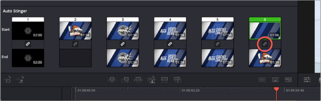
Unlinking the Start and End Stinger (circled red) lets you use different stingers coming in and going out
Replay Title Palette Allows Up to Six Favorite Titles
You can access a six slot favorite titles palette in Replay by choosing Show Titles Palette from the Titles tab option menu. Then simply drag your desired title template into one of the numbered slots below. You can then trigger that title template by pressing the corresponding title button on the Replay Editor.
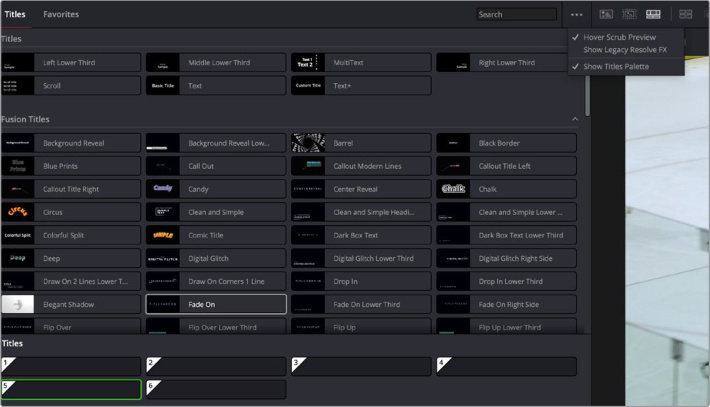
The Replay Titles Palette
Mono Audio Appears on Both Left and Right Channels When Added to Stereo Tracks
DaVinci Resolve 21 has changed the behavior when adding mono audio to stereo tracks. Adding a mono audio clip to a stereo timeline now plays the mono clip on both the left and right channels. Previously it was added to the left channel only. In the Fairlight timeline, this clip is shown in a darker color on the right channel to show that the effect is extrapolated across channels.
Improved Waveforms, Markers and Fades Display for Shorter Edit Timeline Tracks
In DaVinci Resolve 21, when working with shorter tracks in the edit page, the display of those tracks has been changed to maximize the amount of information displayed on the smallest of track sizes. Specifically
Audio waveforms are still visible.
Markers will reduce in size, not just disappear.
Fade handles and transitions will still be usable.
The status icons and clip name won’t occlude each other.
Clip names can be turned off.
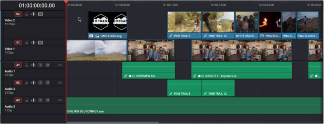
The normal sized timeline tracks

The smallest sized timeline tracks
Source Timelines Support Destination Track Selectors
You can now use Destination Track selectors in Source Timelines to limit tracks when using dual timeline editing.
DRT Timeline Import Supports Link and Conform Options
When importing a DaVinci Resolve Timeline (.drt) file into a project, a new Import Timeline dialog opens, showing you the timeline settings, and a checkbox option to set project settings based on the imported timeline. You can also now can check the box “Automatically link to existing media pool clips” to save you a step from manually relinking the files in the Media Pool.
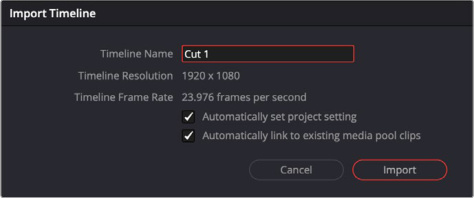
The Import Timeline dialog
Compare Timelines with Timeline Backup Snapshots
If you wish to see what changes you’ve made to a timeline against any of its previously backed up timelines, you can right-click on the timeline and select Compare with Timeline Backup to open up the Compare Timeline window.
The Compare Timeline window shows the two timelines stacked together, highlighting their differences. You can choose which backup to compare it to from the drop-down menu at the top of the window. For more information on using the Compare Timeline window, see Chapter 34, “Creating and Working with Timelines” in the DaVinci Resolve Reference Manual.
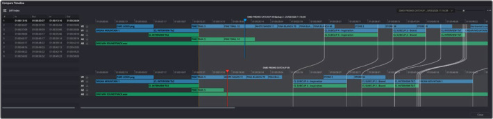
Comparing the current timeline against a previous backup
Subtitle Inspector Supports Find and Replace
You can now find and replace specific words or phrases across an entire subtitle track, using the subtitle inspector. To activate the find and replace tool, click on the search icon in the upper right of the subtitle inspector.
The first selection option lets you choose whether to highlight any words containing the text, or limit it to finding the whole word only.
Then type in the search field the text you want to find, then press the Search button.
Once a term is found, it will be highlighted in yellow in the Caption tab, and you can scroll through found items by clicking on the backwards and forwards arrows next to the search button. A numerical indicator shows how many “hits” the tool found, and what specific instance of that hit is currently selected.
Checking the Replace box, will open up the replace tool, letting you enter the text you want to replace the initial search tool. Click the Replace button will overwrite the selected instance, while Replace All will replace all instances of that search in the subtitle track with the new term.
Clicking on any caption in the caption tab will instantly load it into the Caption box, letting you modify the found text.
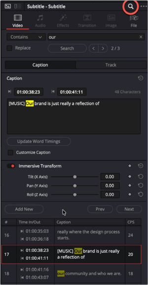
Clicking on the search icon (circled red) in the Subtitle Inspector reveals the search and replace tools. Found instances are highlighted in yellow throughout all the captions.
Tracks Index Lets You Show or Hide Tracks
You can now show or hide tracks from the Tracks Index in the Edit page, by clicking on the eye icon to the left of the track.
Hiding V1 using the Tracks tab in the Index
Edit EDL Clip Name in the Edit Index
You can now directly edit the EDL Clip Name field in the Edit Index. You can turn on this column by right-clicking the column header and checking EDL Clip Name. Clicking in the column allows you to add or edit the clip name in the text field.
Audio Transcription Offers External Subtitle Word Timing
DaVinci Resolve 21 now has the ability to perform word timing analysis on manually entered or imported captions. This means that word level highlighting no longer requires you to generate subtitles in DaVinci Resolve, and when you make corrections to internally generated subtitles, you can reanalyze the caption to get accurate word timing for animated subtitles.
Click on Update Word Timings to adjust the timing
of the subtitle clip after a change is made.
To retime a subtitle / caption:
1 Select the subtitle clip you want to retime on the timeline.
2 In the Video Inspector Caption tab, press the Update Word Timings button.
Select Synchronize Word Timings from the context
menu to retime all subtitles on a track
To retime all subtitle clips on a subtitle track:
1 Right-Click on the subtitle track header.
2 Select Synchronize Word Timings from the context menu.
You can also import transcriptions for media pool clips and have Resolve analyze the timing by right-clicking on a clip and selecting AI Tools > Audio Transcription > Import and Detect Timing.
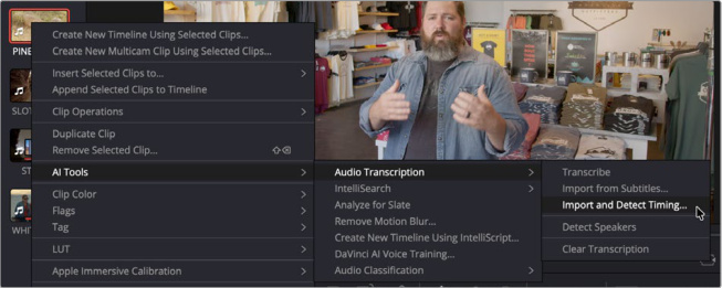
Importing a subtitle for a media pool clip, and detecting its timing.
IntelliScript Supports Final Draft Imports
In addition to plain text files, Intelliscript now will let you import Final Draft (.fdx) files to use to match and generate a timeline based off a script using clips in your media pool.
Edit Page Timecode Display can Show Frames, Subframes or Audio Samples
You can now view timecode in the Edit page timeline with Frames, Subframes, and Audio Sample information instead of just timecode. To change the display, right-click on the Timecode display in the Timeline, and select your option from the dropdown menu.
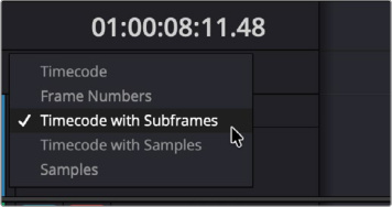
Choosing a different timecode display type by right-clicking on the timecode box.
Up to 2x Faster Speed Warp Metal Option on macOS
DaVinci Resolve 21 on macOS now offers a Speed Warp Metal option for Motion Estimation in the Retime and Scaling controls. This is a specifically enhanced version of Speed Warp that takes advantage of the Mac's hardware. It should dramatically speed up the DaVinci Neural Engine Speed Warp operations.
Select all Transitions in the Cut and Edit Pages
There is a new menu command that will automatically select all transitions in a timeline, or in a set inout range. It can also be limited by the track selector controls.
Timeline > Select Transitions
Paste and Remove Attributes
For Clip Color, Markers and Flags
Clip Color, Markers, and Flags are now parameters that can be selected for Paste Attributes and Remove Attributes commands.
To Retain Image Position
When using the Paste or Remove Attributes window, there is now a new checkbox for Retain Image Position in the Crop section. This allows you to choose whether to lock the crop parameters in place when you resize the image using the Transform tool.
Switch Audio Channels for Multiple Selected Clips via the Context Menu
You can now switch audio channels for multiple clips at once in the timeline, by selecting and rightclicking on the audio clips you want to change, then choosing another channel option from Audio Channel in the context menu.,
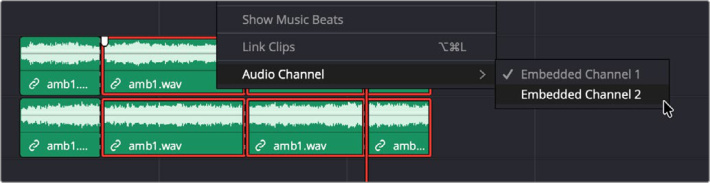
Switching the audio channels of multiple clips
Edit Page Source Tape Supports Stereoscopic 3D and Multicam Clips
DaVinci Resolve 21 now supports Stereoscopic 3D and Multicam clips when using the Source Tape Viewer in the Edit page.
Subtitle Fade Controls
Subtitle clips in DaVinci Resolve 21 now have fade-in and fade-out controls similar to those on video and audio clips. Dragging the fade handles on either side of the clip lets you quickly set the fade length for each.
Media
Media Pool Tabbed Layouts
The Media Pool now allows you to create tabs as shortcuts to specific bins. These tabs will be displayed in their own tab bar at the top of the Media Pool, and Media Pool windows in other pages. Tabs can be set for conventional bins, as well as smart and power bins.
To create a new bin tab, right-click on a bin and select “Open as New Tab” from the contextual menu. Clicking on the tab name, instantly opens that bin in the Media Pool. Further bin navigation in an open tab will replace the active bin with the newest and most current bin selection.
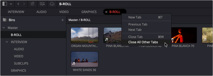
Media Pool Tabs, showing the right-click context menu
Right-clicking on a tab will give you the following options:
New Tab: Creates a new tab (Command T).
Previous / Next Tab: Navigates to the previous or next tab in the tab bar.
Close Tab: Closes the current tab (Command-W) (CTL-W on Windows and Linux).
Close All Other Tabs: Closes all other tabs except the current one.
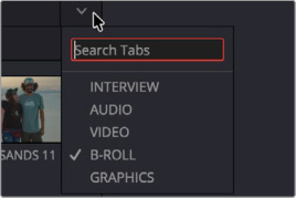
If you end up with many tabs, you can search for specific tabs using the dropdown to the right of the tab bar. Clicking this icon will give you a list of current tabs, and a search box. Note that this search box is for tab names only, and will not return results for media pool clips.
Clicking on the dropdown icon in the right side of the tab bar will let you search for tabs
Thumbnail, List and Metadata Views Can Be Set Per Bin
Bins can now be set to permanently open in a specific layout view (Thumbnail, Metadata, and List) regardless of the current bin view settings. For example, this would let you always open a folder full of audio clips in the List view, where thumbnails can be superfluous.
To set a layout view for a bin:
1 Select the view you want the bin to always open as.
2 Right-click on the bin you want to apply this view to.
3 Select Always Open in XXX View, where XXX will be the name of the view that you’ve chosen.
DaVinci Resolve will remember this bin view across sessions, but it will not affect other users and machines using the same project.
Star Ratings For Clips
You can now rate Media Pool clips from one to five stars in the Shot & Scene Metadata Panel, as well as still photos from multiple Photo Page controls.
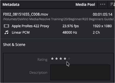
Click on the star rating to set it, and you can click again on a rated clip to re-rate it. You can clear a rating by clicking again on it’s existing rating level.
You can sort by Rating in the List View of the media pool, use Rating as a Smart Bin criteria, and sort an album by Rating in the Photo page.
Giving a clip a four star rating in the Shot & Scene metadata.
Cut Page Supports Smart Bin Views
The Cut Page now lets you view and create Smart Bins in its Media Pool view. You can access any Smart Bin in a project by clicking on the Media Bin dropdown in the upper left of the media pool.
New smart bins can be created by clicking on the + sign in this dropdown.
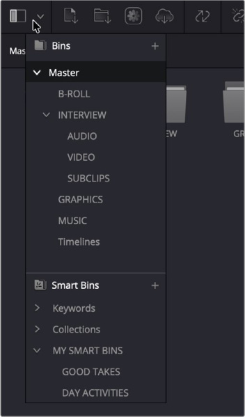
Smart Bins are accessible in the Cut Page by clicking on the Media Bin dropdown menu in the upper left.
Export Media Bin Thumbnails as a PDF
You can now export the thumbnails in a Media Pool bin as a PDF file. The resulting file gives you a digital “contact sheet” of sorts that let you quickly get an idea of what clips are inside a particular bin. The PDF respects the thumbnail image size set in the Media Pool. The view will default to trying to fit the thumbnails on a single page PDF file, however with very large or custom sorted bins the exported PDF will result in one large expanded document rather than broken into pages.
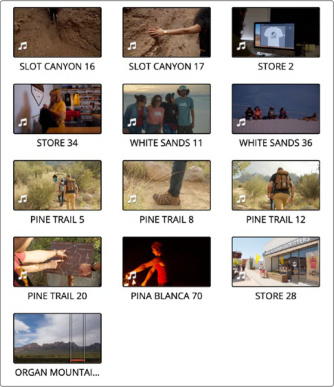
To export a PDF of Media Pool bin thumbnails: Open the bin you want to export, click on the Media Pool 3-dot option menu and select Export as PDF from the context menu. Then choose where to save it.
A PDF export of a Media Pool bin
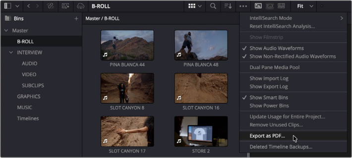
Choosing Export as PDF from the Media Pool option menu
Automatic Smart Bin and Clip Filter for Offline Clips
You can now set up a Smart Bin or Clip Filter (for the Color Page) to automatically gather all offline clips. This gives you a one bin solution for relinking media, regardless of where it is throughout your project.
To set an Automatic Smart Bin for Offline Clips: Check “Automatic smart bin for offline clips” in DaVinci Resolve > Preferences > User > Editing > Automatic Smart Bins.
Use Custom Metadata in Smart Bins, Clip Filters, Data Burn-in and Naming Tags
You can now use any Custom Metadata fields you’ve previously created in the Metadata Editor as criteria for Smart Bins, Clip Filters, Data Burn-ins and Tags.
Customize Project Poster Frames
You can now set a custom Poster Frame for the Project thumbnail in the Project Manager directly from the Media Pool. This lets you visually categorize all your projects at a glance.
To set a Project Poster Frame:
1 Select a clip in the Media Pool that you want the new poster frame to be from.
2 Scrub over the clip until the frame you want shows up in the thumbnail image.
3 Right-click the clip and select Clip Operations > Set Project Poster Frame.
Transcription Column in List View
There is now a Transcription Column in the Media Pool list view. The column is there as a visual indicator. A clip that has been transcribed will only have the first several words written in the Transcription column, but transcription searches will match the whole transcription.
Keyboard Shortcuts to Set Thumbnail List or Metadata Views
You can now set keyboard shortcuts to set the Media Pool view to Thumbnail or Metadata views. You can find these options in the Keyboard Customization panel, in Panels > Media Pool > View Type.
Reset Audio Clip Attributes
There is now a simple icon in Clip Attributes, that lets you reset the Audio Clip Attributes back to their original state.
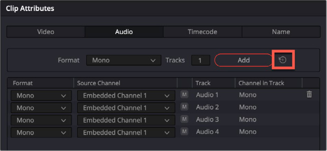
Clicking on the reset icon (red) will reset the audio clip attributes to their original state.
Color
MultiMaster Trim Manager
DaVinci Resolve 21 has made managing your HDR grade trims simpler with the new MultiMaster Trim Manager. This tool allows you to manage multiple grade trims from a single timeline. The main node graph (including Pre and Post Group and node stack layers) serve as the hero grade for your timeline, while additional trim layers are grades that you can apply on top of the hero grade for each deliverable.
For example, you can color grade your master 4000 nit HDR timeline, and simultaneously setup and manage trims for HDR 1000 and SDR Rec.709 output.
To enable the MultiMaster Trim Manager select Color > MultiMaster Trim Manager. You will see the window shown below. To start, toggle the trim passes switch at the top left of the window.
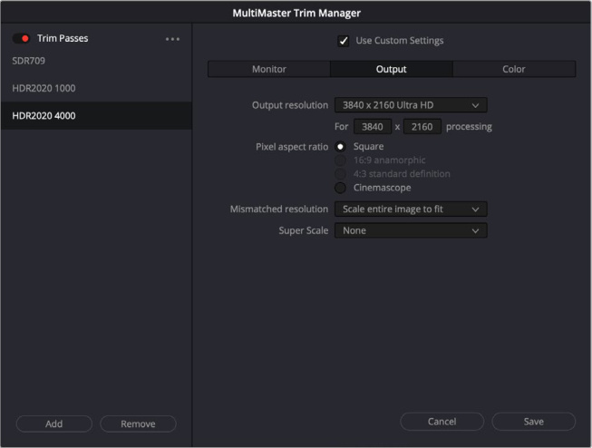
The MultiMaster Trim Manager
In this window, you can create and manage as many trims as you need for your timeline. Add or remove trims by pressing the appropriate button. The trims can be renamed by clicking on the trim name in the list, and typing in a new name. Each trim can also be configured with custom monitoring, output and color management output color space settings.
By default, each trim enables an After Clip node graph, Before Group node graph, After Group node graph, Before Timeline node graph and an After Timeline node graph. You can also enable/disable any of these node graph elements from the Trim Manager window’s 3-dot option menu.
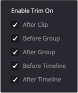
The Enable Trim On Selector
You can toggle your active trim using the 3-dot option menu in the Color page node graph. The selected trim’s name will be displayed at the top of the node graph to easily identify what trim is active.
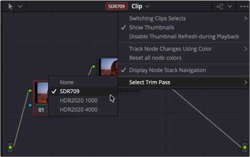
Select Trim Pass in the Node Graph option menu
You can also set your blanking (at either a clip or timeline level) per trim in the Output Sizing palette. To do so, enable the Use Trim blanking checkbox in order to set the blanking at a trim level. Note that this feature is independent of the node stack layers that you enable for the main clip grade.
Finally, when it’s time to output in the Deliver page, you can select the specific Trim Pass grade that you want render for each output under video settings.
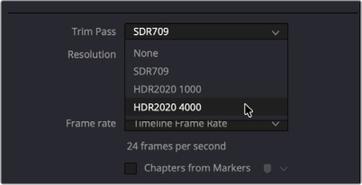
Select the Trim Pass you wish to output
in the Deliver page Video Render settings.
Render AI Magic Mask 2 as an External Matte
You can now render a Magic Mask as a separate matte node. This lets you use the resulting magic mask frames externally as an alpha source for a variety of different effects and purposes.
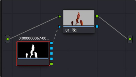
The external matte node created by rendering the Magic Mask
To do so select from the 3-dot option menu, Render in Place Magic Mask, then set a render location for the cached frames.
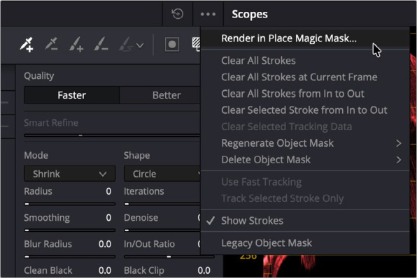
To create the external matte, select Render in Place Magic Mask from the option menu
Clip Groups Support Grade Versioning
You can now use grade versioning on clip groups in addition to individual clips. Versioning your clip groups allows you to create and manage multiple looks for all of the common clips within a group. When using node stack layers you can now have multiple versions of your Pre-Clip and Post-Clip node graphs.
Individual clips in the group can not have different group versions, selecting a version for a group affects all clips in that group.
You can create or switch versions from right-clicking on a grouped clip in the timeline and selecting Groups and its submenus.
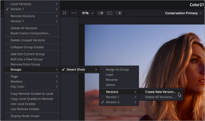
Creating a new version of a Clip Group from the context menu of a clip in the Color page timeline
Node Graphs can be Viewed as a Layer List
The node graph now has a new Layer List view, accessed by clicking on its icon in the upper left of the node graph.
This mode shows all of your nodes as a stacked list of layers. The layers bottom to top are determined by your node order. Node 1 is the bottom most layer, and any additional nodes added are stacked on top as they are created or re-arranged in the node tree.
Layers will let you enable / disable, lock, and add / remove nodes using their appropriate icons. More functionality is planned for later releases. There is also a preview thumbnail and an icon list of tools that have been added to the node for each layer.
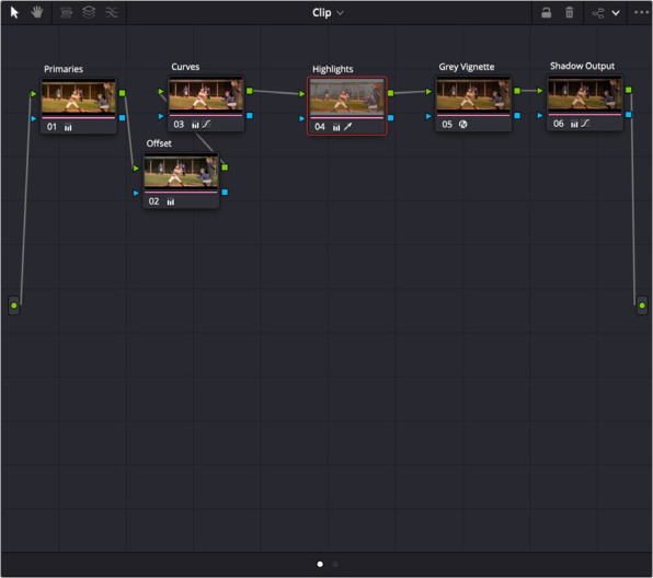
The node graph in node view
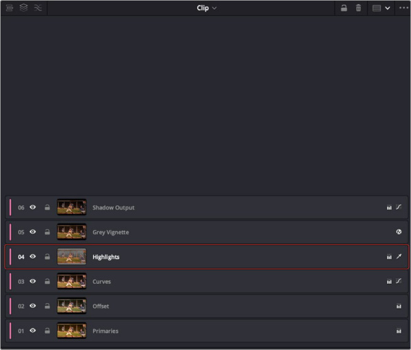
The same graph in Layer View (top left arrow)
Node Stacks Support up to Eight Layers
The maximum number of node stack layers in DaVinci Resolve 21 has been increased from four to eight.
Film Look Creator adds Aurora Preset and Fade Rolloff Controls
The Film Look Creator in DaVinci Resolve 21 adds a new Aurora preset designed to replicate a high contrast, colorful film look, reminiscent of common modern day film stock. The main Aurora preset shows how the core look is intended to be used, though for best results you may want to add additional contrast.
The original footage
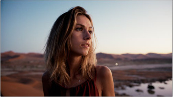
The new Aurora core look applied
In addition, two new controls were added to the effect.
Color Settings
Fade Rolloff: Adjust this slider to determine how gently the black level gets stopped at the fade threshold.
Film Gate
Softness: Adjusts the blurriness of the edges of the film gate.
Shared Node Support for Stereoscopic 3D Clips
Stereoscopic 3D clips can now use Shared Nodes (a node that can be simultaneously updated across all other instances of that node in the grades of other clips) just like normal 2D clips.
Customizable HDR and Nit Scopes Ranges
In HDR projects you can now customize the HDR Parade scopes with custom ranges. Adjusting these ranges stretch the waveforms inside the scope, which allows you to focus on just a specific portion of the waveform.
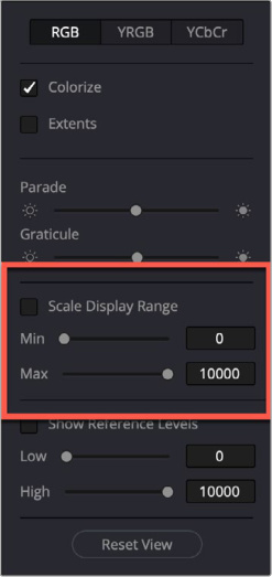
Checking the Scale Display Range box lets you focus the parade scope on just a specific part of the waveform.
HDR Vivid Improvements
HDR Vivid support has received multiple improvements in DaVinci Resolve 21 including:
The HDR Vivid toolset is now available on the DaVinci Resolve Mini Panel.
A Color timeline filter to show clips based on HDR Vivid analysis and trim status.
Falls back to last working trim if the manual trim exceeds the HDR threshold.
An HDR indicator on each timeline thumbnail after analysis
A Mastering display dropdown selection in the HDR Vivid project settings.
A new Tone mapping mode selection for low light grading in the Color page HDR Vivid controls.
ACES AMF Improvements
DaVinci Resolve 21 has added more improvements for the handling of ACES AMF sidecar files.
Displays AMF transform name.
Custom ACES AMF folder support in project settings.
AMF tree selection from the project settings ACES AMF option menu.
Support for project level look transforms.
Indicator for the current working location.
Reset Dolby Vision and HDR Analysis from the Option Menu
You can reset the Dolby Vision and other HDR analysis from the three-dot option menu in their respective tabs in the Color page.
Adobe RGB Colorspace and Gamma Support
For the Photo page introduction, DaVinci Resolve 21 now supports Adobe RGB colorspace and gamma.
OpenFX 1.5 Color Management APIs for Colorspace Aware Effects
DaVinci Resolve now supports OpenFX 1.5 Color Management APIs, which should provide more robust and accurate color handling when using and creating OpenFX tools.
Advanced Color Panel Controls for 2.39 and 2.4 Safe Area
The DaVinci Resolve Advanced Panel now lets you choose 2.39 and 2.4 aspect ratios for the Safe Area display, you can access these using the shift down, A/C Mode (Safe) selection on the T-Bar panel and then directly select 2.39 or 2.4 on the center panel screens.
Multiple User Projects Support Color Management Bypass
In DaVinci Resolve 21, you can now bypass Color Management in a Multi User project the same way you would do in a Single User project. Select Bypass Color Management from the context menu when you right-click on a clip in the Color timeline.
Pasting Tracking Data Between Power Windows Retains Original Shape
In DaVinci Resolve 21, when you paste tracking data between Power Windows, the paste will now retain its original shape.
Resolve FX
Resolve FX Video Collage Updated
The Video Collage Resolve FX now supports separate tile fill and border controls similar to the Picture in Picture effect described above.
Picture in Picture
Picture in Picture is a new Resolve FX that lets you superimpose a smaller video window on top of another full frame video clip. Picture in Picture allows you to see multiple subjects at once, each informing the context of the other. This technique has existed from almost the beginning of television as an analog effect, and now its fully updated digitally with a wide variety of settings and parameters that let you dial in just the look you want.
First in either the Cut or Edit pages, create a timeline that has the background full sized video on the main track, and the video that you want to use for the smaller picture on a track above it.
From the effects tools, add the Picture in Picture effect to the top clip, the one you wish to be smaller, and in the inspector adjust accordingly.
From there you can adjust the parameters in the inspector to get just the exact framing and shape that you want. You can also move, adjust the ratio, and scale the Picture in Picture inside the viewer using the Open FX Overlay view.
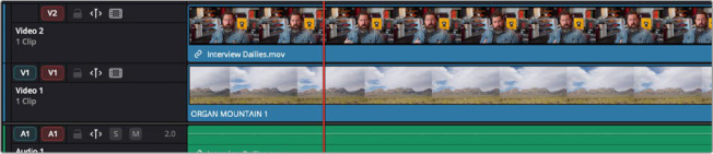
Placing the video elements in the timeline. The background video goes on the bottom track, while the smaller picture is placed on top.
Alternatively, in the Color page we will add the Picture in Picture effect to the node tree from the Effects Library, however initially the background of the node will be black, not transparent. We will need to add an Alpha Output to the node graph to pass the transparency information to the timeline. Right-click anywhere in the Node Graph and choose Add Alpha Output from the context menu. This will add a small blue output box to the node graph, and then connect the blue alpha output of the Picture in Picture node to the Alpha output to complete the effect, like in the example below.
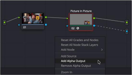
Creating an Alpha Output, and connecting the Picture in Picture’s blue alpha channel to that output.
From there you can adjust the parameters in the inspector to get just the exact framing and shape that you want. You can also move, adjust the ratio, and scale the Picture in Picture inside the viewer using the Open FX Overlay view.
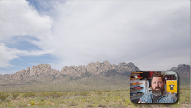
The Picture in Picture output in the viewer
Content
Adjusts the parameters of the source video for the smaller picture
Zoom: Zooms the PiP source in or out.
Pan: Pans the PiP source horizontally.
Tilt: Tilts the PiP source vertically.
Position
Adjusts the position and size of the Picture in Picture. You can also adjust these parameters in the viewer by dragging in the Open FX Overlay mode.
Position X/Y: Adjust the position of the PiP window in the frame.
Width: Adjusts the width of the PiP window.
Height: Adjusts the height of the PiP window.
Style
These tools adjust the shape and layout of the window itself.
Rounding: Adjust the level of the corner rounding of the PiP window, from right angles (0) to circle (1).
Rotation: Allows you to rotate the PiP window.
Opacity: Sets the opacity of the PiP window.
Border: Checking this box applies a colored border to the PiP window, and activates the toolset below.
Border Width: Adjust the width of the window’s border.
Border Color: Change the color of the window’s border.
Border Opacity: Change the opacity of the window’s border.
Fill Matches Border: Checking this box sets the background of the window to be the same color as the border color.
Fill: Checking this box draws a background seen behind transparent content in the frame, and opens the toolset below.
Fill Color: Change the color of the fill.
Fill Opacity: Change the opacity of the fill.
- Drop Shadow: Checking this box puts a drop shadow under the PiP window, and opens the toolset below.
Strength: Adjusts the strength of the drop shadow.
Color: Changes the color of the drop shadow.
Drop Angle: Changes the angle at which the drop shadow appears.
Drop Distance: Changes the distance between the PiP window and the drop shadow.
Expand: Grows or shrinks the drop shadow.
Blur: Adjusts how much blurring the drop shadow has.
- Use Alpha: Checking this box uses the tool’s alpha channel for compositing.
Immersive
VR180 and VR360 Standard Immersive Workflow Support
DaVinci Resolve 21 now supports VR180 and VR360 workflows for standard immersive formats. This lets you edit and create content for a wide variety of VR headsets and platforms, not tied to a specific manufacturer. You can also mix and match VR180 and VR360 in immersive timelines with automatic crop and refit. The sheer variety of resolutions, formats, and frame rates involved in VR do require some initial setup though.
Immersive Project Settings
Before importing VR media into the media pool, you must first open your Project Settings and select Master Settings > Immersive workflows > Standard Immersive. This setting will activate the immersive toolset in DaVinci Resolve.
After selecting the Standard Immersive Workflow, select the resolution is for VR180 in 1:1 or VR360 in 2:1 aspect ratio.
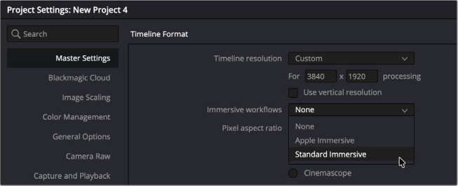
Set your Immersive workflows setting to Standard Immersive before adding clips to the media pool
Clip Attributes
Once your project settings are set up, and you import all of your immersive clips into the media pool, you must manually set the proper clip attributes to identify them as VR clips. To do so, select all of your clips, right-click on one of them and select Clip Attributes from the context menu.
In Clip Attributes’ Video tab, make sure that the correct Stereoscopic Mode, and Projection Format attributes are set to match your specific VR Camera’s footage. Once set, click OK.
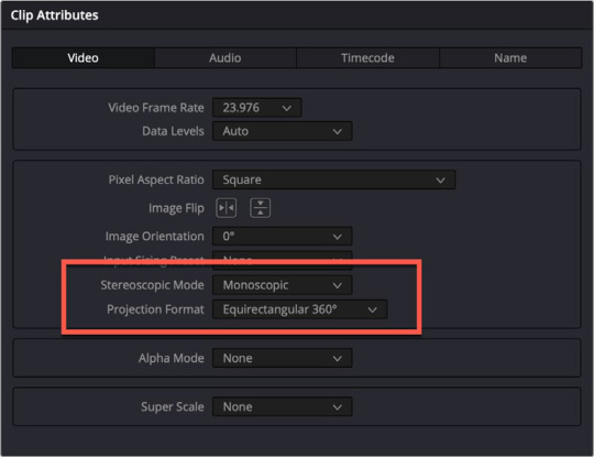
Set your Stereoscopic Mode and Projection format in Clip Attributes for all your clips.
Immersive Viewer
DaVinci Resolve 21 has a new Immersive Viewer mode that can be used in the Media, Edit, Color and Fairlight pages. This viewer mode lets you toggle between a standard 2D view, and a simulated VR headset in Viewport mode. This lets you preview your VR footage outside the headset. You can also click and drag inside the viewer in this mode to rotate the view.
Please note this is a view only, it does not actually re-orient your footage.
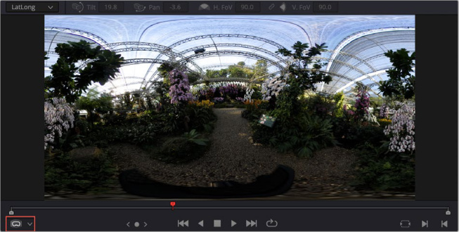
The Immersive Viewer (red rectangle) in LatLong view, showing an equirectangular 360 image.
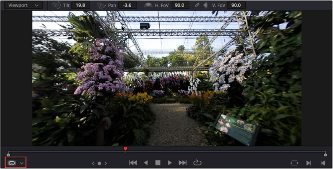
The Immersive Viewer (red rectangle) in Viewport mode, showing the same 360 image, simulated in a headset.
Immersive Viewer Selection
Lets you choose how the VR content will be displayed in the Viewer.
LatLong: Views the content in an equirectangular projection.
Viewport: Simulates a VR headset in the viewer, letting you adjust head position and field of view.
Tilt: Tilts the head view on the Y (vertical) axis. You can click and drag either left or right in the numeric field, or up and down inside the viewer to change the view.
Pan: Tilts the head view on the X (horizontal) axis. You can click and drag either left or right in the numeric field, or left and right inside the viewer to change the view.
H. FoV: Lets you change the field of view to match the headset’s FoV, horizontally. You can click on the small link icon to lock the Horizontal and Vertical fields of view together.
V. FoV: Lets you change the field of view to match the headset’s FoV, vertically. You can click on the small link icon to lock the Horizontal and Vertical fields of view together.
Immersive Transform
When a Standard Immersive project setting is selected, it activates the Immersive Transform tool in the Video Inspector. The Immersive Transform parameters let you orient the VR video clip in a specific direction, so you can set what your viewer will initially be looking at when facing forward in the headset. You can also use this tool to orient two immersive clips together so that the transition between them makes aesthetic sense.
While these parameters can be animated and are keyframable, it’s better to leave them static and let your viewer tilt, pan and roll using their natural head movements. Forcing directional movement in VR is likely to induce nausea.
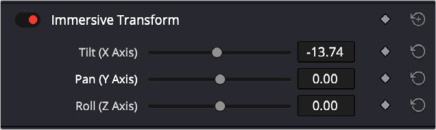
The Immersive Transform tool in the Video Inspector
Immersive Transform
Lets you adjust the initial position of the footage inside the VR content.
Tilt: Tilts the footage on the Y (vertical) axis. You can drag the slider to change the position.
Pan: Tilts the footage on the X (horizontal) axis. You can drag the slider to change the position.
Roll: Tilts the footage on the Z (roll) axis. You can drag the slider to change the position.
Immersive Delivery
In the Deliver page there is a new VR 180/360 delivery preset, designed to be compatible with the widest range of VR headsets, including Meta Quest. You can however tweak these setting to specifically tailor the output for your particular headset. This Delivery setting will automatically add additional VR format data to the file name, that will trigger the proper type of playback settings in most VR players.
The VR 180/360 delivery preset
Apple Immersive Workflows Now Support Foveated Rendering
You can now use and adjust the Foveated Rendering parameters for Apple Immersive Workflows. Foveated rendering allows an increase in perceived pixel density in a specific area of the image, while deprioritizing other areas. This lets you still have the full visual impact of the scene while dramatically reducing its size and bandwidth requirements, for say streaming over the internet.
To access the Foveation settings, open a clip in the Color Page, select 3D from the toolbar, then click on the Foveation icon. Two tabs, Clip and Timeline will adjust the foveation for a single clip, or all clips on the timeline respectively. The controls allow you to set the area of Foveation in the immersive viewer.
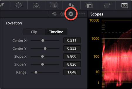
The Foveation settings (circled red) in the Color Page
Fusion LatLong Patcher and PanoMap Support for Standard Immersive Workflows
In Fusion, use the LatLong Patcher, PanoMap and other tools to handle and transform VR180 and VR360 video sources.
LatLong Patcher allows a customizable field of view to match your headset.
Panomap adds immersive rotation and ILPD retargeting.
Fairlight
Folder Tracks
Folder Tracks are new to Fairlight in DaVinci Resolve 21, and this feature lets you select a group of tracks then combine them into a single composite view. The original tracks are still unchanged, but now Can be viewed only taking only take up one track’s worth of space on the timeline.
This lets you easily change the scale and context of your timeline even as it gets more complex. For example, you may have four separate gunfire sound effects tracks for a running action scene that you now want to combine into a single folder track, so you can work on the music score without the UI cluttered up by irrelevant tracks.
The resulting folder track will still show all the individual track positions, just indented under the track folder. You can then click on the disclosure triangle in the top left of the folder track to collapse it, making a single track out of it. Clicking on the disclosure triangle again will reopen the folder track.
The original clip’s positions are now portrayed in a minimized view and without any waveform data. Any track colors assigned will still be visible, and you can rename the folder track by clicking on its track name. Closed folder tracks don’t have level meters, but you can restore them by just opening the folder track again.
Editing is supported on the composite view of the folder track, which can be very convenient and powerful when working with many elements. Solo and Mute buttons are available at the folder level as well, which is useful if you want to solo or mute an entire group of tracks at once.
You can permanently restore the view of the original tracks by simply deleting the folder track.
TIP: You can also create a folder track inside another folder track for even more granular track organization. Folder tracks support a maximum of three levels of nesting.
The Fairlight timeline before adding tracks A13-A17 into a folder track,
The folder track open, showing the enclosed tracks
The folder track closed using the disclosure triangle to the left of the track header.
To add Tracks to a Folder Track:
1 Select two or more tracks on the Fairlight Page
2 Right-click on one of the selected tracks
3 Choose Add Tracks to New Folder.
To delete a Folder Track and restore the original track positions:
1 Right-click the folder track.
2 Choose Delete Track from the context menu.
Go to Mouse Pointer Using the C Key
Just like the Edit Page, pressing the “C” key will instantly snap the playhead to wherever the pointer is in the Fairlight timeline. This instant snapping makes navigating longer timelines easier and more efficient.
Fusion
Krokodove Toolset Integrated into Fusion and Edit Effects
The popular third party Krokodove Fusion tools have been integrated directly into DaVinci Resolve and Fusion, bringing in more than a hundred new motion graphics effects and tools.
A brief description of the toolset follows:
3D
| Mapped Duplicate 3D | Creates a 3D grid of duplicated objects in X, Y and Z space.<br>Images can control, offset, rotation, scale, timing... of those objects. |
|---|
Image Tools
| Bounding Box | Draws a rectangle from a selected channel. Threshold controls determines<br>the rectangle size. |
|---|---|
| Color Map | Map a texture to one or more flat colors. The colors can be set manually or<br>detected automatically. |
| Connect | Connect draws a continuous line between individual points. Points can be<br>individually positioned creating ‘way-points’ for the drawn line. |
| Dither | Dither is a filter that introduces a pattern of noise that can create a sense of<br>shading. Dither methods can be used to create a distinct, crunchy texture. |
| Extend | Extend replicates edge pixels on a horizontal or vertical axis,<br>creating a repeating pixel effect. |
| Fragments | Fragments chops an image in separate pieces which you can then fade<br>in/out using the Range options. |
| Grow | Grow allows an image to grow or disappear starting from one or more<br>seed locators. |
| Grow Color | Grow Color extends the color at the edge of an image, filling transparent<br>parts by stretching the edges. |
| Microwaves | Microwaves generates radiating highlights from a central point, this<br>tool simulates beams of light with additional controls to change the<br>overall shape. |
| Pack | Pack creates patterns of stacked shapes within a specified color channel. |
| Painterly | Painterly is a filter effect, that creates a stylized ‘artwork’<br>look over an image or graphic. |
Image Tools
| Rasterize is a filter effect, taking an image and converting it into a series | |
|---|---|
| Rasterize | of shapes, including dots, squares or diamonds. You can use this tool to<br>generate a half-tone style image. |
| Time Mapper | Time Mapper combines different times of a sequence controlled<br>by an external image map. |
| Worm | Worm creates a combination of straight and curved lines using<br>specified points. |
Image Color Tools
| Invert | Invert the color, luminance or hue. |
|---|---|
| Match Color | Use Match Color to pick a tone, such as shadows, midtones,<br>or highlights and replace it with a color. |
| Recolor provides controls to substitute colors. Nominate one or more | |
| Recolor | source colors and replace the selections with new colors using the<br>color swatch. |
| Replace Color | Nominate a source color and replace it with a correction. |
| Threshold | Use Threshold to isolate a specific, narrow range of color or brightness<br>of a specified channel. Controls in this tool let you adjust the tolerance of<br>the selection. |
Image Create Tools
| Blobs | Blobs generates circular shapes at specified points. |
|---|---|
| Generate | Generate is a tool used to add texture to a source input. Creating a<br>greyscale image, Generate builds a seemingly randomized noise pattern. |
| Lines | The Lines tool creates patterns of one or multiple line sets, and generates<br>multiple levels of repeating lines. |
| Pattern | Pattern builds an array of tessellated shapes, creating a full-frame pattern. |
| Shapes | The Shapes tool creates multiple levels of concentric shapes,<br>including squares and circles. |
Image Pixel Tools
| Average | This tool averages multiple subsequent frames in a sequence,<br>creating a frame blending effect. |
|---|---|
| Bevel | The Bevel tool creates an internal bevel around an image, simulating depth. |
| Channel Shifter | Channel Shifter separates the RGBA channels and provides controls to<br>offset/blur/scale the channels. |
Image Pixel Tools
| Clean Edges | Remove frame edge pixels by duplicating or using a solid color.<br>Frame border. |
|---|---|
| Deflicker | Deflicker removes regional or global flickering of subsequent frames. |
| Duplicate | Replicates the incoming image along a pattern/shape of choice. |
| Extrude | The Extrude tool distorts the edge of an image, creating the<br>illusion of depth. |
| Noise | The Noise tool creates a pixellated pattern. Colors can be randomly<br>generated or selected |
| Plastic | Plastic is a filter tool creating a synthetic bevel effect. This tool simulates<br>a plastic film/sheen over the source image. |
| Positioner | Positioner is a corner pinning tool with source and destination controls. |
| Push | Push creates a ‘slide’ effect. Connect a second image,<br>sliding from one image to the other. |
| Rest | Rest will shift pixels to rest on a single line, warping the<br>top or bottom of an image along a path. |
| Seamless | Seamless Mirrors the opposite edge, blending with the original. |
| Seamless Loop | Seamless Loop provides controls to change the timing of a comp,<br>building a seamless looping sequence. |
| Sort | Sorts pixels on color value |
Image Position Tools
| Contour<br>mage Vector Tools | The Contour tool creates an outline around an image, generating repeating<br>lines through a gradient. |
|---|---|
| Vector Visualisation | Generates an overlay that visualizes motion vector direction/velocity. |
Image Vector Tools
Image Warp Tools
| Bend | Bend is a radial warp tool, bending an image using a three point spline. |
|---|---|
| Directional Scale | Directional Scale is a single sided scaling tool,<br>stretching an image in a specified angle. |
| Kaleidoscope | Kaleidoscope is a classic filter tool, creating radial mirroring of the<br>image to create a kaleidoscopic effect. |
| Mirror | Reflects the image around an arbitrary axis, flipping the image<br>along a specified line. |
Image Warp Tools
| Offset | Offset will shift image pixels controlled by another image, displacing an<br>image on the horizontal or vertical axis. |
|---|---|
| Radial | Moves pixels radially away or to the center instead of scaling them,<br>creating a dent distortion. |
| Relative Transform | Uses a second input to warp/distort using position, rotation,<br>and scale controls.<br>The transformation pivot is detected from the incoming image<br>and can be set, relative to the actual pixel data. |
| Segment Transform | Divides the frame into square-shaped segments, with angle and scale<br>distortion applied to each segment. |
| Shear | The Shear tool applies an angular shear effect. Use the additional<br>input to determine the shear intensity. |
| Shuffle | The subdivided frame is repositioned within the image. |
| Spherize | Spherize is a radial and cylindrical deformation tool, creating a round<br>style warp within a specified region. |
| Stretch | The Stretch tool lengthens an image along any predefined axis,<br>pixel stretching along a specified line. |
Modifiers
| Beat modifier adds controls to drive animation in Frames per Beat or Beats | |
|---|---|
| Beat | per Minute. Other controls include Start and End time, Attack, Decay,<br>Sustain, Release. |
| Color Switcher | When working with multiple color palettes, this modifier allows to easily<br>switch between those palettes or rotate colors within this palette. Setting up<br>requires to connect individual channels (RGBA) to the different outputs.<br>(A script here would be handy). |
| Random | Random modifier adds a random value generator to any control. It allows<br>you to set the Min and Max range of output values to be randomized.<br>It also has controls to set the new random values over a frame range<br>allowing a smooth transition from one value to another over time. |
Text Modifiers
| Formula | Custom tool as a modifier. |
|---|---|
| Modifier that allows the user to import a txt format file, or enter manually. | |
| From File | Controls allow text to be displayed a line at a time for a fixed or<br>custom duration. |
| Juggle | Modifier that randomly mixes characters. |
| Write | Write On style modifier that has options to add a cursor/caret at the tail of<br>the text, as if it being typed from a device. Also has the option to add a<br>Prefix to a sentence that is constantly visible, IE not affected by the write<br>on effect. |
Improved Macro Editor
The Fusion macro editor in DaVinci Resolve 21 has been greatly improved to be more intuitive, with a live preview of what your macro will look like in the inspector as you’re building it. This lets you build even the most complicated macros with quicker iteration feedback and more clarity.
Some effects aren’t built with one tool, but with an entire series of operations, sometimes in complex branches with interconnected parameter controls. Fusion provides many individual effects nodes for you to work with but gives users the ability to repackage them in different combinations as selfcontained “bundles” that are either macros or groups. These “bundles” have several advantages:
They reduce visual clutter in your node tree.
They ensure proper user interaction by allowing you to restrict which controls from each node of the macro are available to the user.
They improve productivity by allowing artists to quickly leverage solutions to common compositing challenges and creative adjustments that have already been built and saved.
Using the Macro Editor
All macros start with the individual tools on the node editor. Select the tool or tools in the node editor that you wish to create a macro from, then right click on one of them and select Macro > Create Macro from the context menu. This will open up the Macro Editor.
The Fusion Macro Editor
The Macro Editor is comprised of three main areas:

Enter a name for your macro
At the top is the Macro Name, this is where you give a name to your macro that will be added to the tool list, and right-clicking on the magic wand icon lets you choose an image for the new macro’s thumbnail icon.
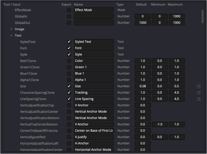
The Macro Edior
To the left is the macro editor itself. This will list every parameter of every tool that you selected in column view. Each parameter will have a checkbox in the Export Column. Checking this box will add that parameter to your macro, unchecking the box will exclude that parameter from your macro.
The Macro Editor Columns:
Tool/Input: The internal Fusion parameter name or Input connection.
Export: Check this box to use this parameter in your macro, uncheck it to exclude it.
Name: A text field that lets you name or rename this parameter’s title in the macro.
Type: The data type that this parameter expects to receive.
Default: This field lets you pre-set the default value of the parameter.
Minimum: This field lets you set the minimum allowed value of the parameter.
Maximum: This field lets you set the maximum allowed value of the parameter.
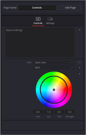
Enter a name for your macro
To the right is the live Inspector Preview, that shows what your macro will look like as you build it. This visualization is valuable, allowing you to add, remove, or edit controls during the macro’s development. This live preview doubles as an interactive environment, allowing you to drag and drop controls in the live preview, changing their order. You can drag a parameter up or down in the list order, or even to another page. You can add a new page of parameters, or rename an existing one. The layout buttons in the lower left of the Macro Editor let you further adjust the look of your macro:
Add Separator: Adds a separator line to the macro to separate unrelated controls. This can be removed by unchecking its export box.
Add Spacer: Adds a blank space to the macro to separate unrelated controls. This can be removed by unchecking its export box.
Add Nest: Adds a nested disclosure list to the macro. Add the nest, then drag parameters into it that you want hidden until the disclosure icon has been clicked. You can set its initial open/close state in the Default column (1 is open, 0 is closed). This can be removed by unchecking its export box.
As you are building your macro, it can be useful to test it live inside the node editor without having to save and import it back again each time. In the Macro Editor three-dot option menu, you can select Copy Macro as you’re working, then paste your work in progress directly to the node editor to see how it actually performs in Fusion.
Once your Macro is finished, you can use the option menu to save it back to Fusion in a variety of ways.
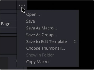
Macro Editor Option Menu
The Macro Editor’s Option Menu:
Open: Loads an existing macro into the Macro Editor.
Save: Saves the current work in progress.
Save As Macro: Saves the current macro (a single node with custom parameters).
Save As Group: Saves the current macro as a group (a container of individual nodes that can be expanded later).
Save to Edit Template: Saves the macro as an edit template that will show up in the effects list in the Cut or Edit pages. You can choose between Title, Generator, Effect, or Transition templates.
Choose Thumbnail: Lets you load an image to use as the macro’s thumbnail picture.
Show in Folder: Opens the file location where your macro is saved.
Copy Macro: Copies the current state of the macro, allowing you to paste it into the node tree to test it.
Fusion Animation can be Creatively Driven by Fairlight Audio
A new Fairlight Animator modifier is available in Fusion tools. This powerful new modifier connects Fusion to Fairlight’s audio engine, enabling automatic animation based on audio analysis. The Fairlight Animator processes audio from timeline clips or media pool sources, analyzing audio levels to drive any numerical control.
You can access this tool, by right-clicking a fusion parameter, and selecting Modify With > Fairlight Animator from the context menu.
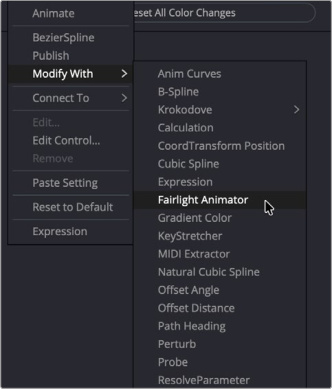
Choosing the Fairlight Animator modifier
Clicking on the Modifiers tab in the inspector will reveal it’s controls.
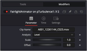
The Fairlight Animator controls
Support for OGraf HTML Graphics and Lottie Animations
DaVinci Resolve 21 adds support for OGraf (.json) and Lottie (.lottie) HTML based animation on macOS and Windows. Animation, whether it’s something you found online or created from scratch, can now be added directly to your timeline. Simply export your .json or .lottie file, then drag and drop it into your Media Pool just like any other media. You can also drop it straight into the timeline, where it will be recognized and treated like a fully rendered animation clip. The alpha background is also recognized, so transparency is maintained. You can simply drop the clip over another layer and it will composite correctly, which makes it perfect to use as a stinger or transition.
Additionally, Fusion now includes a new node called OGrafLoader. This handy tool lets you easily load your OGraf or Lottie files directly into your composition.
Text+ and MultiText Support Spell Checking
As a nice quality of life improvement for the grammatically challenged, DaVinci Resolve 21 includes a multi-language text spell checker for Text+ and MultiText in Fusion. Any spelling mistakes are highlighted red in both the viewer and inspector. Right click on a word to preview suggested replacements or ignore the word.
Font Improvements Including Color Fonts and Emojis
Emoji support is included for both Text+ and MultiText, giving you the flexibility to add expressive icons and visual accents directly within your text for more dynamic and engaging designs.
You can add emoji directly into the text fields by pressing Control-Command-Space on macOS, and Windows key-. (period) on Windows.
In addition, Text+ and MultiText features a more robust font support, with improved support for color fonts, bitmap fonts, and font styles. With supported color fonts, the Text+ inspector shows additional controls for Color Palettes under Advanced Controls, where you can select display options for the font.
Certain emoji fonts like Noto Color Emoji only have emoji glyphs, and not letters. So when you type Latin characters with those fonts, they will not appear in the text.
If you use a regular font then type emoji, Fusion will detect that and automatically use an emoji font instead. But it doesn’t substitute the other way around. There is a Fusion preference to determine which emoji font to use.
Improved MultiText for Position, Pivot, Alignment and CSV Import
MultiText in Fusion has been improved the position, alignment controls, and CSV import, as well as adding pivot adjustments to the Layout tab.
Support for USD SDK 25.11 with Hydra 2.0 API for Storm Renderer
Fusion has been updated to USD SDK 25.11 with Hydra 2.0 API for the Storm renderer. This enhancement brings you an improved Fusion USD environment along with a handy new addition to the uRenderer called Neye. This fresh AOV provides camera-relative normals, giving you even more flexibility in your workflow.
USD Support for 3D Matte Objects and Textures
We’ve enhanced our USD geometry tools with new “Is Matte” controls for greater creative flexibility. These controls are now built directly into the USD geometry tools and are also available in the uReplaceMaterial tool. The Is Matte feature functions like Fusion 3D tools, allowing you to occlude background objects or create clean alpha channel cutouts by punching holes where needed.
USD Projector and USD Catcher Tools
Introducing the new USD Projector and uCatcher tools. The uProjector node lets you project images directly onto USD geometry, casting images across any objects in your USD scene, instantly transforming how your USD objects look. Working hand-in-hand with the uProjector, the uCatcher tool captures the texture-mode projections and converts them to textures that seamlessly apply to your connected geometry. Together, these tools open up creative possibilities for dynamic texture mapping in your USD workflows. Projection has also been added to the uCamera tool; connect an image to the new Image Input and new tabs will appear. As with Camera 3D, these tabs also include Image and Material, allowing a camera-matched image plane for convenience. These tools are described in detail below.
uProjector [uPj]
The uProjector node
uProjector Node Introduction
The uProjector node is used to project an image upon USD geometry. This can be useful in many ways: texturing objects with multiple layers, applying a texture across multiple separate objects, projecting background shots from the camera’s viewpoint, image-based rendering techniques, and more. The uProjector node is just one of several nodes capable of projecting images and textures. Each method has advantages and disadvantages.
Projected textures can be allowed to “slide“ across the object if the object moves relative to the uProjector, or, alternatively, by grouping the two with a uMerge so they can be moved as one and the texture remains locked to the object.
The uProjector node’s capabilities and restrictions are best understood if the uProjector is considered to be a variant on the uDisk node.
Lighting must be turned on for the results of the projection to be visible.
The light emitted from the projector is treated as diffuse/specular light. This means that it is affected by the surface normals and can cause specular highlights.
Enabling Shadows causes uProjector to cast shadows.
The light projected by a uProjector will affect all objects downstream of the uProjector in the USD node tree.
Alpha values in the projected image do not clip geometry in Light mode. Use Texture mode instead.
If two projections overlap, their light contributions are added.
To project re-lightable textures or textures for non-diffuse color channels (like Specular Intensity or Bump), use the Texture projection mode instead:
Projections in Texture mode only strike objects that use the output of the uCatcher node for all or part of the material applied to that object.
Texture mode projections clip the geometry according to the Alpha channel of the projected image.
See the section for the uCatcher node for additional details.
uCamera Projection vs. uProjection Node
The uCamera node also provides a projection feature, and should be used when the projection is meant to match a camera, as this node has more control over aperture, film back, and clip planes. The uProjector node was designed to be used as a custom light in USD scenes for layering and texturing. The projector provides better control over light intensity, color, decay, and shadows.
Inputs
The uProjector has two inputs: one for the scene you are projecting on to and another for the projected image.
SceneInput: The orange scene input accepts a USD scene. If a scene is connected to this input, then transformations applied to the spotlight also affect the rest of the scene.
ProjectiveImage: The white input expects a 2D image to be used for the projection. This connection is required.
Basic Node Setup
As an example, the uProjector node below is used to project a light (Background1) onto USD primitives. All the set elements are connected into a uMerge, which outputs the projected set into a larger scene with camera, lights, and other elements. The uProjector node could be fed into either uMerge node to return the same result.
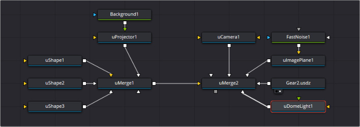
uProjector texturing groups of shapes to construct a set
Inspector
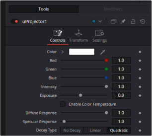
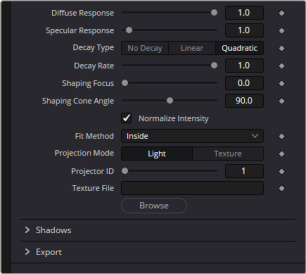
uProjector controls
Controls Tab
Color
The input image is multiplied by this color before being projected into the scene.
Intensity
Use this slider to set the Intensity of the projection when the Light and Ambient Light projection modes are used. In Texture mode, this option scales the Color values of the texture after multiplication by the color.
Exposure
This will change how much light will expose a scene; this is similar to Intensity.
Color Temperature/Enable
This sets the color temperature of a light source. Its default is 6500K, which is daylight temperature.
Diffuse Response
Controls the amount the light will contribute to the Diffuse color of a material.
Specular Response
Controls the amount the light will contribute to the Specular color of a material.
Decay Type
A uProjector defaults to Quadratic Decay which causes the intensity to fall off with Distance. Linear decay will produce a similar look, but No Decay means the light has equal intensity at all points in the scene.
Decay Rate
The rate at which the light from the projection will fall off over distance. The lower the decay rate, the stronger the projection.
Shaping Focus
Adjusting this control will focus the projection from the edges to the centre.
Shaping Cone Angle
The Shaping Cone Angle refers to the width of the cone where the projector emits its full intensity. The larger the angle, the wider the cone angle, up to a limit of 180 degrees.
Normalize Intensity
With this checkbox enabled the Width and Height of the projection is set to default values. Unchecking reveals individual Width and Height values which can be adjusted manually.
Fit Method
The Fit Method determines how the projection is fitted within the projection cone.
The first thing to know is that although this documentation may call it a “cone,” the uProjector and Camera USD nodes do not project an actual cone; it’s more of a pyramid of light with its apex at the camera/projector. The uProjector node always projects a square pyramid of light—i.e., its X and Y angles of view are the same. The pyramid of light projected by the Camera USD node can be non-square depending on what the Film Back is set to in the camera. The aspect of the image connected into the uProjector/Camera USD does not affect the X/Y angles of the pyramid, but rather the image is scaled to fit into the pyramid based upon the fit options.
When both the aspect of the pyramid (AovY/AovX) and the aspect of the image (height * pixelAspectY)/(width * pixelAspectX) are the same, there is no need for the fit options, and in this case the fit options all do the same thing. However, when the aspect of the image and the pyramid (as determined by the Film Back settings in Camera USD) are different, the fit options become important.
For example, Fit by Width fits the width of the image across the width of the Camera USD pyramid. In this case, if the image has a greater aspect ratio than the aspect of the pyramid, some of the projection extends vertically outside of the pyramid.
There are five options:
Inside: The image is uniformly scaled so that its largest dimension fits inside the cone. Another way to think about this is that it scales the image as big as possible subject to the restriction that the image is fully contained within the pyramid of the light. This means, for example, that nothing outside the pyramid of light ever receives any projected light.
Width: The image is uniformly scaled so that its width fits inside the cone. Note that the image could still extend outside the cone in its height direction.
Height: The image is uniformly scaled so that its height fits inside the cone. Note that the image could still extend outside the cone in its width direction.
Outside: The image is uniformly scaled so that its smallest dimension fits inside the cone. Another way to think about this is that it scales the image as small as possible subject to the restriction that the image covers the entire pyramid (i.e., the pyramid is fully contained within the image). This means that any pixel of any object inside the pyramid of light always gets illuminated.
Stretch: The image is non-uniformly scaled, so it exactly covers the cone of the projector.
Projection Mode
Light: Projects the texture as a diffuse/specular light.
Texture: When used in conjunction with the uCatcher node, this mode allows re-lightable texture projections. The projection strikes only objects that use the catcher material as part of their material shaders.
One useful trick is to connect a uCatcher node to the Specular Texture input on a USD Material node (such as a Blinn). This causes any object using the Blinn material to receive the projection as part of the specular highlight. This technique can be used in any material input that uses texture maps, such as the Specular and Reflection maps.
Shadows
Since the projector is based on a spotlight, it is also capable of casting shadows using shadow maps. The controls under this reveal are used to define the size and behavior of the shadow map.
Enable Shadows: The Enable Shadows checkbox should be selected if the light is to produce shadows. This defaults to selected.
Shadow Color: Use this standard Color control to set the color of the shadow. This defaults to black (0, 0, 0).
Density: The Shadow Density determines the transparency of the shadow. A density of 1.0 produces a completely transparent shadow, whereas lower values make the shadow transparent.
Softness: Controls the softness of the shadow.
Softness Quality: Controls the quality of the softness.
Shadow Map Size: The Shadow Map Size control determines the size of the bitmap used to create the shadow map. Larger values produce more detailed shadow maps at the expense of memory and performance.
Shadow Map Bias: If no shadows are seen, this tool can fine tune the shadow map to make it visible in the scene.
Shadow Map Offset: Offset the value of the Shadow Map Size.
Common Controls
Transform and Settings Tabs
The remaining Transform and Settings tabs are common to many USD nodes. Their descriptions can be found in “The Common Controls” section at the end of this chapter.
uCatcher [uCa]
The uCatcher node
uCatcher Node Overview
The uCatcher material is used to “catch” texture-mode projections cast from uProjector and uCamera nodes. The intercepted projections are converted into a texture map and applied by the uCatcher material to the geometry to which it is connected.
To understand the uCatcher node, it helps to understand the difference between light-based projections and texture-based projections. Choosing Light from the projection mode menu on the uProjector or uCamera nodes simply adds the values of the RGB channels in the projected image to the diffuse texture of any geometry that lies within the projection cone. This makes it impossible to clip away geometry based on the Alpha channel of an image when using light mode projections.
Imagine a scenario where you want to project an image of a building onto an image plane as part of a set extension shot. You first rotoscope the image to mask out the windows. This makes it possible to see the geometry of the rooms behind the wall in the final composite. When this image is projected as light, the Alpha channel is ignored, so the masked windows remain opaque.
By connecting the uCatcher to the diffuse texture map of the material applied to the image plane, and then switching the projection mode menu in the uProjector or uCamera node from Light to Texture mode, the projected image is applied as a texture map. When using this technique for the example above, the windows would become transparent, and it would be possible to see the geometry behind the window.
The main advantages of this approach over light projection are that the uCatcher can be used to project Alpha onto an object, and it doesn‘t require lighting to be enabled. Another advantage is that the uCatcher is not restricted to the diffuse input of a material, making it possible to project specular intensity maps, or even reflection and refraction maps.
NOTE: The uCatcher material requires a uProjector or uCamera node in the scene, set to project an image in Texture mode on the object to which the uCatcher is connected. Without a projection, or if the projection is not set to Texture mode, the uCatcher simply makes the object transparent and invisible.
Inputs
The yellow Scene input accepts USD geometry, (i.e. a uShape or a USD asset via a uLoader).
Basic Node Setup
The input of the uCatcher node is the geometry of the USD asset that will receive the projected texture. The output of the uCatcher node will be a uMerge where other assets, lights or cameras can be composited.
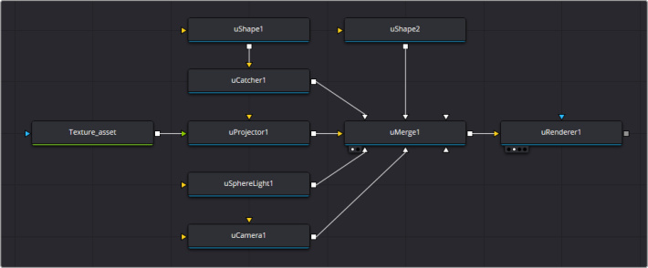
A uCatcher node gets input from the geometry node (uShape1) that is used for receiving the texture projection, then outputs to a uMerge node.
Inspector
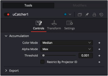
uCatcher controls
Controls Tab
The Options in the Controls tab determine how the uCatcher handles the accumulation of multiple projections.
Color Mode
The Color mode menu is used to control how the uCatcher combines the light from multiple projectors. It has no effect on the results when only one projector is in the scene.
Alpha Mode
The Alpha mode is used to control how the uCatcher combines the Alpha channels from multiple projectors. It has no effect on the results when only one projector is in the scene.
Threshold
The Threshold can be used to exclude certain low values from the accumulation calculation. For example, when using the Median Accumulation mode, a threshold of 0.01 would exclude any pixel with a value of less than 0.01 from the median calculation.
Restrict by Projector ID
When active, the uCatcher only receives light from projectors with a matching ID. Projectors with a different ID are ignored.
Common Controls
Transform and Settings Tabs
The Transform and Settings tab in the Inspector is also duplicated in other USD nodes. These common controls are described in detail at the end of this chapter in “The Common Controls” section.
Fusion Global in-out controls for USD Loader
When importing a USD file into stand alone Fusion, there is now an option to set a global in-out range.
3D Renderer now Supports Creating and Using Cryptomatte
Cryptomatte layers and metadata can be generated for both objects and materials when using the Renderer3D’s hardware renderer. This new functionality allows you to create multiple soft mattes for specific 3D objects or materials from a rendered scene. The newly created layers can be interpreted by Fusion’s Cryptomatte tool, natively reading the embedded mattes and simplifying the task of isolating rendered elements for compositing. They may also be saved to an OpenEXR file for later use.
Relief Map Tools
New to Fusion are the Relief Map tools that can improve 3D object realism. What makes Relief mapping truly special compared to traditional bump maps is its ability to create self-occlusion. These two additions, CreateReliefMap and ReliefMap, are designed to help the creation of detailed surface textures.
CreateReliefMap is a new filter tool that creates the required image for the ReliefMap node. The generated depth map will be used to create simulated texture and lighting effects. CreateReliefMap has controls to adjust depth scale and smoothing to influence how strong or subtle the relief appears.
ReliefMap is a new 3D tool that generates height based surface detail to 3D shapes. Using an image, the ReliefMap will erode portions of a 3D shape effectively creating depth information for a surface. This method of sculpting will directly change part of a material’s normal/displacement mapping, enabling the creation of intricate textures without manually modeling every detail.
Both tools are described in detail below.
CreateReliefMap [CRM]
The CreateReliefMap node
CreateReliefMap Node Introduction
Create Relief Map is a companion tool that creates the required image for the ReliefMap node. It generates a relief map by taking a height field and generating values that are used to modify the object’s surface normals.
When fed into a Relief Map it creates simulated texture and lighting effects. CreateReliefMap has controls to adjust depth scale and smoothing to influence how strong or subtle the relief appears.
Inputs
The single yellow input receives a 2D image.
Basic Node Setup
In this example, a series of shape nodes are used to feed the input of the CreateReliefMap node. The output of this node would then be fed into a ReliefMap node to adjust the depth of the 3D surface.

A 2D shape is input from the sRender node to the CreateReliefMap node.
For example a simple Arrow Shape is created and fed into the CreateReliefMap node.

The source shape fed into the CreateReliefMap node
After making adjustments in the CreateReliefMap node, you would then connect it’s output to a ReliefMap node.
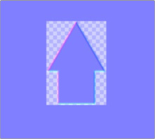
The resulting output of the CreateReliefMap that would be fed into the ReliefMap node
Then you would make adjustments in the ReliefMap Node to actually apply the shape to the connected 3D image.
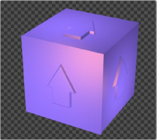
The resulting output of the ReliefMap node applied to a 3D shape
Inspector
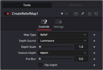
CreateReliefMap controls
Controls Tab
Map Type
There are 3 options, Relief, Relaxed Cone and Cone. All three methods use a combination RGB and Alpha to generate the relief map. Relaxed Cone and Cone may produce more accurate results at a performance cost.
Depth Source
Use the dropdown menu to choose which source to use to generate depth data for the relief map.
Depth Scale
Increasing the value of the slider increases the depth of the relief map.
Texture Depth
Options to match or change the bit depth of the relief map.
Pre Blur
Adjust slider to increase pre blur to the source image before generating the Relief Map.
Flip Depth
Checking this box will invert the depth mapping.
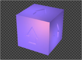
The same shape above, with the Flip Depth checkbox selected.
Common Controls
Transform and Settings Tabs
The remaining Transform and Settings tabs are common to many nodes. Their descriptions can be found in “The Common Controls” section at the end of this chapter.
ReliefMap [3RM]
The ReliefMap node
ReliefMap Node Introduction
Relief Map is a 3D tool that generates height based surface detail to 3D shapes.
Using an image passed through its companion Create Relief Map node, the Relief Map will erode portions of a 3D shape effectively creating depth information for a surface. This method of sculpting will directly change part of a material’s normal/displacement mapping, enabling the creation of intricate textures without the need to manually model every detail. What separates Relief mapping from bump maps, is that Relief can occlude itself, creating natural lighting interactions.
Relief Map’s RGB channels are set to normals values and the alpha is the height/depth.
Inputs
Background Input: The yellow input is for a material input, (i.e. Blinn, Ward, CookTorrance or Phong).
Relief Map Input: The white input is to connect a 2D image via the Create Relief Map node you want to use as the Relief Map texture.
Basic Node Setup
In this example, a Text+ node is passed through a Create Relief Map node to generate the data required for the Relief Map to be applied to a Shape3D. For the Relief Map, the generated map is connected to the white input and a material to its yellow input. The output of the Relief Map is connected to 3D geometry (Shape3D) and merged into a 3D scene.
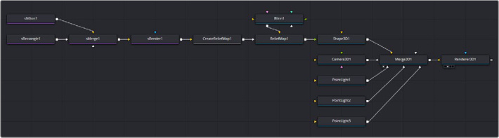
The ReliefMap node combining information from both Relief Map and a Blinn nodes before passing the finished relief data to apply to a Shape3D node.
Inspector
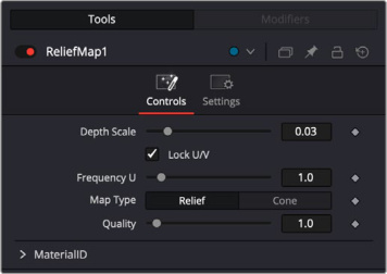
ReliefMap controls
Controls Tab
Depth Scale
The slider allows you to expand or contract the overall depth of the relief map. Increasing the depth scale will amplify the overall distance of depth.
Lock U/V
When enabled the U/V channels are scaled uniformly. When disabled the frequency of each channel can be adjusted independently.
Map Type
There are two methods to apply a relief map, Relief and Cone. Both use RGBA values to generate data, but Cone will provide better quality and faster shading at a performance cost.
Quality
Increasing the value quality slider will fine tune the quality of the result. This is seen most when using the Relief map type.
Common Controls
Transform and Settings Tabs
The remaining Transform and Settings tabs are common to many nodes. Their descriptions can be found in “The Common Controls” section at the end of this chapter.
Multi-Inspector
The Multi-Inspector is a powerful new feature in Fusion v21 that allows users to edit common properties across multiple selected tools simultaneously. This streamlines workflows by eliminating the need to adjust identical parameters on each tool individually. When multiple tools are selected in the Flow, the Multi-Inspector presents controls that are common to all of them. Users can then adjust these shared parameters, and the changes are applied simultaneously to every selected tool.
Changing Common Inspector Properties
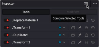
The Combine Selected Tools icon in the Inspector header
When multiple tools are selected, a new toggle icon in the Inspector header now allows them to be combined into a single set, showing only those controls that are common to all selected tools. Dragging one of these controls, or typing in a new value, sets all of the selected tools at once. This can greatly speed up many common workflows, allowing simultaneous tweaks to numerous different tools without requiring full instancing or copy & paste.
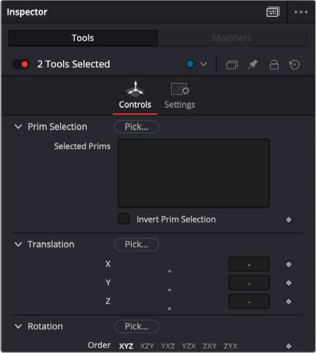
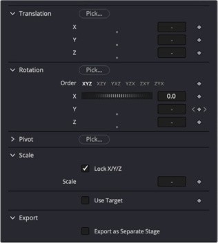
Two uTransform nodes combined, let you set parameters for both tools simultaneously.
If selected controls have different values for different tools, then control knobs and values will be hidden. Dragging on the value edit field will add or subtract an offset to each tool’s control individually, maintaining differences without setting them to be identical. Size and Scale controls will apply a scaling factor instead, preserving the ratio between each tool. Additionally, holding the Opt/Alt key while dragging will switch to between offsetting and scaling mode, allowing even more control.
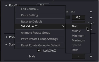
The Set Values To context menu
When multiple controls are combined, the control’s context menu gains a new set of Set Values To options, including First, Middle, Minimum, Maximum, Spread, and Jitter. These options work with the range of values in the selected controls, and can set them all to a single point in the range, or to spread them all out evenly across that range, or to add a little randomness to each value.
Multilayer Support for Stereoscopic 3D Clips and Deep Images
In Fusion 21, there is now multilayer for Steresocopic 3D and Deep Images.
Color Correction for Deep Images in Fusion
There is a new Deep Color Corrector tool, for color grading deep images. The tool is described in detail below.
dColorCorrector [dCC]
The dColorCorrector node
dColor Corrector Node Introduction
The dColor Corrector node is a comprehensive color node for Deep images with histogram matching, and equalization, hue shifting, tinting, and color suppression.
Controls in the dColor Corrector node are separated into four tabs: Correction, Ranges, Options, and Settings.
Inputs
The dColor Corrector node includes two inputs in the Node Editor.
Input: This yellow input is the only required connection. It connects a Deep image for color correction.
Effect Mask: The optional blue input expects a mask shape created by polylines, basic primitive shapes, paint strokes, or bitmaps from other tools. Connecting a mask to this input limits the color corrector adjustment to only those pixels within the mask. An effect mask is applied to the tool after the tool is processed.
Basic Node Setup
The dColor Corrector node, like many Deep image-processing nodes, receives a Deep image like a Loader node or the MediaIn1 shown below. The output continues the node tree by connecting to another Deep image-processing node or a Merge node.
A dColor Corrector node applied to a MediaIn1 node containing an EXR Deep image file.
Inspector
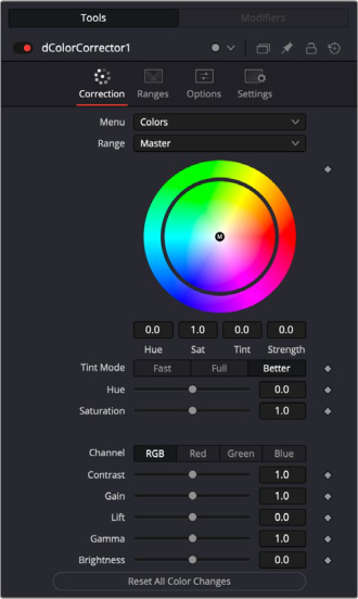
dColor Corrector controls
Correction Tab Colors Menu
The main Correction tab is further separated into four types of correction methods: colors, levels, histogram, and suppress. Selecting one from the menu at the top of the Correction tab causes that method’s controls to appear. The Color method is described in detail below.
Range
This menu determines the tonal range affected by the color correction controls in this tab. The menu can be set to Shadows, Midtones, Highlights, and Master, where Master is the default affecting the entire image.
The selected range is maintained throughout the Colors, Levels, and Suppress sections of the dColor Corrector node.
Adjustments made to the image in the Master channel are applied to the image after any changes made to the Highlight, Midtone, and Shadow ranges.
NOTE: The controls are independent for each color range. For example, adjusting the Gamma control while in Shadows mode does not change or affect the value of the Gamma control for the Highlights mode. Each control is independent and applied separately.
Color Wheel
The color wheel provides a visual representation of adjustments made to Hue and Saturation, as well as any tinting applied to the image. Adjustments can be made directly by dragging the color indicator, or by entering values in the numeric boxes under the color wheel.
The tinting is represented in the color wheel color indicator that shows the color and strength of the tint. The Highlight setting uses a black outline for the color indicator. The Midtones and Shadows use gray color indicators. The Master color indicator is also black, but it has a white M in the center to distinguish it from the others.
The mouse can position the color indicator for each range only when the applicable range is selected. For example, the Highlight color indicator cannot be moved when the Master range is selected.
Holding down the Command or Ctrl key while dragging this indicator allows you to make finer adjustments by reducing the control’s sensitivity to mouse movements. Holding down the Shift key limits the movement of the color indicator to a single axis, allowing you to restrict the effect to either tint or strength.
Tint Mode
This menu is used to select the speed and quality of the algorithm used to apply the hue and saturation adjustments. The default is Better, but for working with larger images, it may be desirable to use a faster method.
Hue
This slider is a clone of the Hue control located under the color wheel. The slider makes it easier to make small adjustments to the value with the mouse. The Hue control provides a method of shifting the hue of the image (or selected color range) through the color spectrum. The control value has an effective range between -1.0 and 1.0, which represents the angle of rotation in a clockwise direction. A value of 0.25 would be 90 degrees (90/360) and would have the effect of shifting red toward blue, green to red, and so on.
Hue shifting can be done by dragging the slider, entering a value directly into the text control, or by placing the mouse above the outer ring of the color wheel and dragging the mouse up or down. The outer ring always shows the shifted colors compared to the original colors shown in the center of the wheel.
Saturation
This slider is a clone of the Saturation control located under the color wheel. The slider makes it easier to make small adjustments to the value with the mouse. The Saturation control is used to adjust the intensity of the color values. A saturation of 0 produces gray pixels without any color component, whereas a value of 1.0 produces no change in the chroma component of the input image. Higher values generate oversaturated values with a high color component.
Saturation values can be set by dragging the slider, entering a value directly into the text control, or by dragging the mouse to the left and right on the outer ring of the color wheel control.
Channel
This menu is set for the Histogram, Color, and Levels sections of the dColor Corrector node. When the red channel is selected, the controls in each mode affect the red channel only, and so on.
The controls are independent, so switching to blue does not remove or eliminate any changes made to red, green, or Master. The animation and adjustments made to each channel are separate. This menu simply determines what controls to display.
Contrast
Contrast is the range of difference between the light to dark areas. Increasing the value of this slider increases the contrast, pushing color from the midrange toward black and white. Reducing the contrast causes the colors in the image to move toward midrange, reducing the difference between the darkest and brightest pixels in the image.
Gain
The Gain slider is a multiplier of the pixel value. A gain of 1.2 makes a pixel that is R0.5 G0.5 B0.4 into R0.6 G0.6, B0.48 (i.e., 0.4 * 1.2 = 0.48), while leaving black pixels totally unaffected. Gain affects higher values more than it affects lower values, so the effect is strongest in the midrange and top range of the image.
Lift
While Gain scales the color values around black, Lift scales the color values around white. The pixel values are multiplied by the value of this control. A Lift of 0.5 makes a pixel that is R0.0 G0.0 B0.0 into R0.5 G0.5, B0.5, while leaving white pixels totally unaffected. Lift affects lower values more than it affects higher values, so the effect is strongest in the midrange and low range of the image.
Gamma
Values higher than 1.0 raise the Gamma (mid gray), whereas lower values decrease it. The effect of this node is not linear, and existing black or white points are not affected at all. Pure gray colors are affected the most.
Brightness
The value of the Brightness slider is added to the value of each pixel in your image. This control’s effect on an image is linear, so the effect is applied identically to all pixels despite value.
Reset All Color Changes
Selecting this button returns all color controls in this section to their default values.
Correction Tab Levels Menu
The main Correction tab is further separated into four types of correction methods: colors, levels, histogram, and suppress. When Levels is selected from the menu, you can remap the white and black points of an image, with a Gamma control to adjust midtones. A histogram provides a view of the tonal distribution in the image to help guide your adjustments. The Level method is described in detail below.
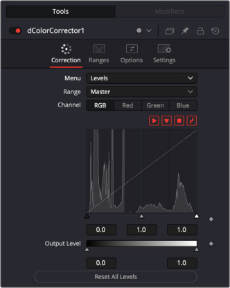
dColor Corrector Levels controls
Range
Identical to the Range menu when Color is selected in the Menu, the Range menu determines the tonal range affected by the color correction controls in this tab. The menu can be set to Shadows, Midtones, Highlights, and Master, where Master is the default affecting the entire image.
The selected range is maintained throughout the Colors, Levels, and Suppress sections of the dColor Corrector node.
Adjustments made to the image in the Master channel are applied to the image after any changes made to the Highlights, Midtones, and Shadows ranges.
NOTE: The controls are independent for each color range. For example, adjusting the Gamma control while in Shadows mode does not change or affect the value of the Gamma control for the Highlights mode. Each control is independent and applied separately.
Channel
This menu is used to select and display the histogram for each color channel or for the Master channel.
Histogram Display
A histogram is a chart that represents the distribution of color values in the scene. The chart reads from left to right, with the leftmost values representing the darkest colors in the scene and the rightmost values representing the brightest. The more pixels in an image with the same or similar value, the higher that portion of the chart is.
Luminance is calculated per channel; therefore, the red, green, and blue channels all have their own histogram, and the combined result of these comprises the Master Histogram.
To scale the histogram vertically, place the mouse pointer inside the control and drag the pointer up to zoom in or down to zoom out.
Display Selector Toolbar
The Display Selector toolbar at the top of the histogram provides a method of enabling and disabling components of the histogram display. Hold the mouse pointer over the button to display a tooltip that describes the button’s function.
Input Histogram: This enables or disables the display of the input image’s histogram.
Reference Histogram: This enables or disables the display of the reference image’s histogram.
Output Histogram: This enables or disables the display of the histogram from the post-colorcorrected image.
Corrective Curve: This toggles the display of a spline used to visualize exactly how auto color corrections applied using a reference image are affecting the image. This can be useful when equalizing luminance between the input and reference images.
Histogram Controls
These controls along the bottom of the histogram display are used to adjust the input image’s histogram, compressing or shifting the ranges of the selected color channel.
The controls can be adjusted by dragging the triangles beneath the histogram display to the left and right.
Shifting the High value toward the left (decreasing the value) causes the histogram to slant toward white, shifting the image distribution toward white. The Low value has a similar effect in the opposite direction, pushing the image distribution toward black.
Output Level
The Output Level control can apply clipping to the image, compressing the histogram. Decreasing the High control reduces the value of pixels in the image, sliding white pixels down toward gray and gray pixels toward black.
Adjusting the Low control toward High does the opposite, sliding the darkest pixels toward white.
If the low value were set to 0.1, pixels with a value of 0.0 would be set to 0.1 instead, and other values would increase to accommodate the change. The best way to visualize the effect is to observe the change to the output histogram displayed above.
Reset All Levels
Clicking this button resets all the controls in the Levels section to their defaults.
Correction Tab Histogram Menu
When the menu is set to Histogram, a histogram display is produced of the input image. If a reference image is also provided, the histogram for the reference image is also displayed. The controls in this tab are primarily used to match one image to another, using either the Equalize or Match modes of the dColor Corrector.
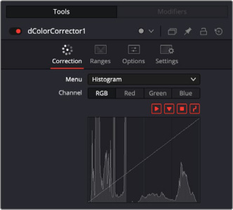
dColor Correction in Histogram mode
Channel
This menu is used to select and display the histogram for each color channel or for the Master channel.
Histogram Display
A histogram is a chart that represents the distribution of color values in the scene. The chart reads from left to right, with the leftmost values representing the darkest colors in the scene and the rightmost values representing the brightest. The more pixels in an image with the same or similar value, the higher that portion of the chart is.
Luminance is calculated per channel; therefore, the red, green, and blue channels all have their own histogram, and the combined result of these comprises the Master Histogram.
To scale the histogram vertically, place the mouse pointer inside the control and drag the pointer up to zoom in or down to zoom out.
Display Selector Toolbar
The Display Selector toolbar at the top of the histogram provides a method of enabling and disabling components of the histogram display. Hold the mouse pointer over the button to display a tooltip that describes the button’s function.
Input Histogram: This enables or disables the display of the input image’s histogram.
Reference Histogram: This enables or disables the display of the reference image’s histogram.
Output Histogram: This enables or disables the display of the histogram from the post-color-corrected image.
Corrective Curve: This toggles the display of a spline used to visualize exactly how auto color corrections applied using a reference image are affecting the image. This can be useful when equalizing luminance between the input and reference images.
Correction Tab Suppress Menu
Color Suppression provides a mechanism for removing an unwanted color component from the image. The Color Wheel control is similar to that shown in the Colors section of the node, but this one is surrounded by six controls, each representing a specific color along the wheel.
To suppress a color in the selected range, drag the control that represents that color toward the center of the color wheel. The closer the control is to the center, the more that color is suppressed from the image.
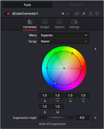
dColor Corrector Suppression controls
Suppression Angle
Use the Suppression Angle control to rotate the controls on the suppression wheel and zero in on a specific color.
Reset All Suppression
Clicking this control resets the suppression colors to 1.0, the default value.
Ranges Tab
The Ranges tab contains the controls used to specify which pixels in an image are considered to be shadows and which are considered to be highlights. The midrange is always calculated as pixels not already included in the shadows or the highlights.
Range
This menu is used to select the tonal range displayed in the viewers. They help to visualize the pixels in the range. When the Result menu option is selected, the image displayed by the color corrector in the viewers is that of the color corrected image. This is the default.
Selecting one of the other menu options switches the display to a grayscale image showing which pixels are part of the selected range. White pixels represent pixels that are considered to be part of the range, and black pixels are not in the range. For example, choosing Shadows would show pixels considered to be shadows as white and pixels that are not shadows as black. Mid gray pixels are only partly in the range and do not receive the full effect of any color adjustments to that range.
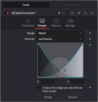
dColor Corrector Ranges controls
Channel
The Channel menu in this tab can be used to examine the range of a specific color channel. By default, Fusion displays the luminance channel when the color ranges are examined.
Spline Display
The ranges are selected by manipulating the spline handles. There are four spline points, each with one Bézier handle. The two handles at the top represent the start of the shadow and highlight ranges, whereas the two at the bottom represent the end of the range. The Bézier handles are used to control the falloff.
The midtones range has no specific controls since its range is understood to be the space between the shadow and the highlight ranges.
The X and Y text controls below the spline display can be used to enter precise positions for the selected Bézier point or handle.
Output the Range You See Now as Final Render
Selecting this checkbox causes the monochrome display of the range shown in the viewers to be output as the final render. Normally, the Color node outputs the full RGBA image, even if the node were left to display one of the color ranges in the view instead. This control makes it possible to use the dColor Corrector node to generate a range’s matte for use as an effect mask in other nodes.
Preset Simple/Smooth Ranges
These two buttons can be used to return the spline ranges to either Smooth (default) or Simple (linear) settings.
Options Tab
The Options tab includes a few very important processing operations including a simple solution when color correcting premultiplied Alpha channels.
dColor Options controls
Histogram Proxy Scale
The Histogram Proxy Scale determines the precision used when creating and calculating histograms. Lower values represent higher precision, and higher values produce a rougher, generalized histogram.
Process Order
This menu is used to select whether adjustments to the image’s gamma are applied before or after any changes made to the images levels.
Apply Mask Inverted
Enabling the Apply Mask Inverted option inverts the complete mask channel for the tool. The mask channel is the combined result of all masks connected to or generated in a node.
Settings Tab
Clipping Mode
This option determines how edges are handled when performing domain of definition rendering. This is mostly important for nodes like Blur, which may require samples from portions of the image outside the current domain.
Frame: The default option is Frame, which automatically sets the node’s domain of definition to use the full frame of the image, effectively ignoring the current domain of definition. If the upstream DoD is smaller than the frame, the remaining area in the frame is treated as black/transparent.
Domain: Setting this option to Domain respects the upstream domain of definition when applying the node’s effect. This can have adverse clipping effects in situations where the node employs a large filter.
None: Setting this option to None does not perform any source image clipping at all. This means that any data required to process the node’s effect that would normally be outside the upstream DoD is treated as black/transparent.
The Settings tab in the Inspector is also duplicated in other nodes. These common controls are described in detail at the end of this chapter in “The Common Controls” section.
User Defined Metadata Variables in Paths, Expressions, and Scripts
A new variables system has been added to Fusion. This new feature builds on Fusion’s already powerful scripting component, making it even more versatile. There are three aspects of this feature.
1 Fusion Preference setup.
2 Using variables in Expressions.
3 Using variables in Saver paths.
Getting started
In preferences, a new category has been added: Variables Map. This can be found in Global and Comp Preferences. Variables can be created and edited at a global level, for all comps, or at a per-comp level. They may also include expressions, and reference other variables.
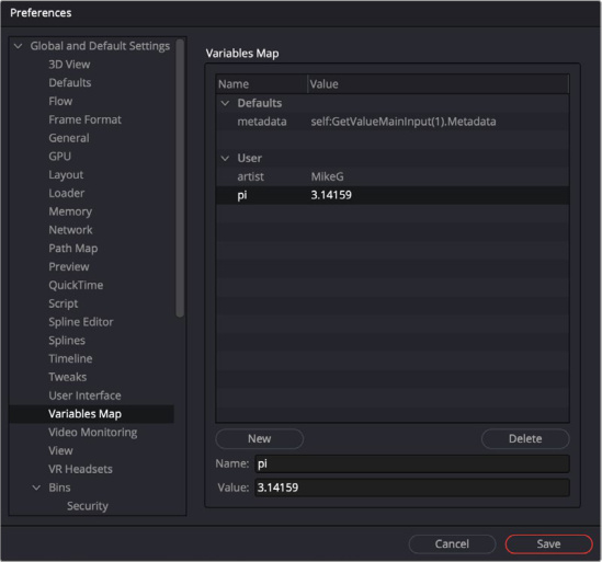
The Fusion Variables Map preference
In an expression you can call Global Variables with fu.vars.[variable name] and Comp Variables comp.vars.[variable name] in expressions.
Variables (both Global and Comp) can be used in a Saver to create a save location or file name.
In Saver’s Filename control, use %{name}. This will call up a list of available categories, including custom variables (from Prefs), clip metadata, or Resolve metadata (on the Fusion Page). Input Metadata variables in Saver will look like %{metadata.metadataname}, and Resolve variables in Saver will look like %{resolve:Resolve Metadata}
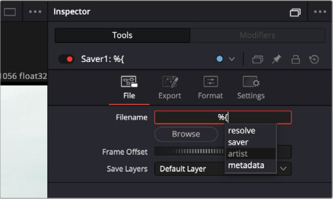
Using a mapped variable in a text field.
In expressions, metadata from an upstream clip can be called using fu.vars.metadata. [name] or comp.vars.metadata.[name]
Additionally, on the Fusion Page, in an expression you can call metadata from Resolve using fu.vars.resolve[“Name”]. Example fu.vars.resolve[“Timeline Name”].
Improved Lens Distort Tool
The Lens Distort tool has been improved with checkerboard calibration and it can now be GPU accelerated.
Motion Vector Layers Generated from Optical Flow
Fusion’s Optical Flow tool has received an update, now outputting motion vectors as discrete layers. The vector channels generated by the Optical Flow tool are now fully compatible with Fusion’s multi-layer pipeline. This modification enables tools that previously utilized vector auxiliary channels to access the newly implemented Vector and Back Vector layers.
The tools that can receive motion vector layers include:
Smooth Motion
Vector Denoise
Vector Transform
Vector Warp
TimeSpeed (Flow Interpolation Mode)
TimeStretcher (Flow Interpolation Mode)
Improved Guides and Rulers
The Guides and Rulers in Fusion 21 have been improved with locked persistence, guide presets and improved snapping.
MediaIn Nodes Show Clip Name
In Fusion 21, instead of showing MediaIn#, MediaIn nodes will now show the clip name instead.
Open Keyframes and Spline Editor as a New Window
For expanded detail, you can now open the Fusion Keyframe and Spline editors in a new resizable window by clicking on the Undock icon in the Keyframes or Spline toolbar.
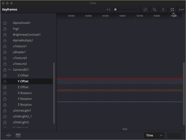
Undocking the Keyframe editor into it’s own resizable window.
Nudge Spline Keyframes
In the Spline editor, you can use the comma (,) and period (.) keys to nudge a Spline keyframe left or right respectively.
Up to 2x Faster Relight Tool
The Relight tool in Fusion is now up to two times faster than the previous version.
Up to 6x Faster Depth Map Tool
The Depth Map tool in Fusion is now considerably faster with up to a six times speed increase over the previous version.
Support for Remote Monitoring of Fusion Previews
Fusion Previews can now be streamed live using DaVinci Resolve’s Remote Monitoring tools and application.
SpeedWarp [SPDw]
The SpeedWarp node
SpeedWarp Node Introduction
SpeedWarp is an AI-powered retiming node that analyses the motion between existing frames to construct new intermediate frames, allowing for smooth slow-motion without stuttering. Using DaVinci’s neural network, SpeedWarp can reconstruct complex motion that traditional interpolation or frame blending would typically blur or distort.
Inputs
Input: The orange input receives the 2D image that is to be affected by the SpeedWarp.
Basic Node Setup
In a simple example, the SpeedWarp node applies a retiming operation on the connected video clip (A001_) then passes that retimed video to the MediaOut node.
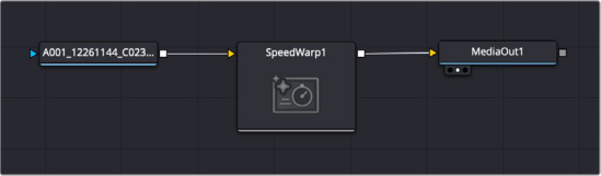
A simple SpeedWarp setup
Inspector
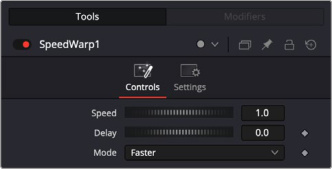
SpeedWarp controls
Controls Tab
Speed
The speed wheel adjusts the speed of the Speed Warp output. By default this is set to 1.0 where no speed change is applied. Changing the speed to 0.5 will halve the speed of the output, 2.0 will double the speed, etc.
Delay
The delay will offset the output starting frame of the Speed Warp. Adding a delay of 10.0 will offset the output by 10 frames forward, a delay of -10.0 will offset the output by 10 frames backward.
Mode
Choose the mode of the SpeedWarp.
Faster: Faster processing for a quicker result.
Better: Higher quality at a performance cost.
Common Controls
Transform and Settings Tabs
The remaining Transform and Settings tabs are common to many nodes. Their descriptions can be found in “The Common Controls” section at the end of this chapter.
General Improvements
Background Rendering
DaVinci Resolve 21 now supports background rendering for certain computationally intensive operations. Currently the operations that can be rendered in the background are Background renders, quick exports and proxy generation. You can also background analysis for transcription and audio classification.When an operation moves to the background, it allows you to continue to work on other operations in the Resolve interface, without waiting for the original operation to finish processing first. Background rendering can still require significant computational resources, so depending on your workstation’s processor, ram, data throughput etc., it may slow down your system unacceptably. As a result, Background Rendering is disabled by default.
While the background tasks are operating, a pop up on the bottom toolbar allows you to monitor their progress.
Background Rendering can be controlled in DaVinci Resolve > Preferences > System > Background Tasks.
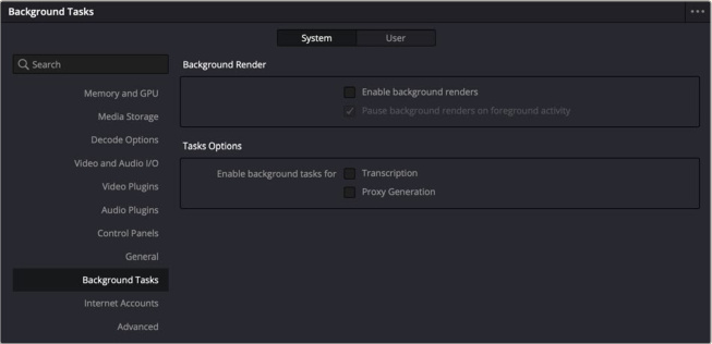
Background Tasks preferences
Background Render: These options control the Background Rendering parameters.
Enable background renders: Checking this box turns on Background Rendering, unchecking turns it off.
Pause background renders on foreground activity: Checking this box will pause the background processes when actively working with the DaVinci Resolve interface. This gives you full computer power for your active work, and continued background processing when you stop.
Tasks Options: These options let you choose which operations to render in the background.
Transcription: Check this box to move transcription tasks to the background.
Proxy Generation: Check this box to move proxy generation tasks to the background.
Expanded Data Burn-In Window
The Data Burn-In window has been overhauled in DaVinci Resolve 21 to be more powerful and flexible with both the Burn-In fields themselves and their positioning.
The Data Burn-In window is still accessed at Workspace > Data Burn-In, and you will need to choose either the Project or Clip tabs at the top. Choosing the Project tab will apply the Data Burn-In to all clips in your timeline. Choosing the Clip tab will apply the Data Burn-In only to the selected clip.
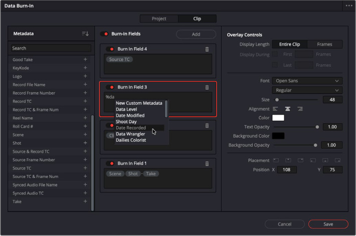
The Data Burn-In window
The Data Burn-in Window is divided into three columns. The left most column is for selecting the Metadata fields used in your burn-in. There is a list of common fields, along with a search box to narrow down results, and the icon to sort them alphabetically up or down. Simply select the “+” icon to add that field to the middle Burn-In Fields column.
The middle column is Burn-In Fields, this lets you customize and format the exact data returned in the field. You can use any combination of typed in text, metadata fields from the left column, and other custom metadata tags for any metadata field. To use custom metadata tags, first type in the “%” sign, then start typing the name of the metadata field you wish to use. A dropdown selection will appear as you type, and simply click on the name of the exact field you want. Each Field has its own off-on toggle, with a master on-off toggle at the top of the column. You can add new blank fields by clicking on the Add button. Selecting a field lets you set it’s Overlay Controls in the right column.
The Overlay Controls let you adjust the font format and positioning of the Burn-In Field in the frame.
Display Length: Determines for how long the field is displayed. You can choose between either the Entire Clip, or Frames to set a custom length.
Display During: When Frames is selected from the Display Length, these controls are activated. Checking the First and / or Last boxes and entering a length in frames, lets you determine when and for how long the field is displayed.
Font: Choose the typeface of the field.
Size: Controls the size of the font.
Alignment: Choose either Left, Center, or Right text justification of the field.
Color: Opens a color picker to choose the color of the font.
Text Opacity: Choose the level of font transparency.
Background Color: Opens a color picker to choose the background color of the field.
Background Opacity: Choose the level of background transparency.
Placement: Choose one of the icons to correspondingly position the field in the frame.
Position X/Y: Enter a value or drag inside the field to position the Burn-In in the frame.
Press the Save button to activate the Burn-In.
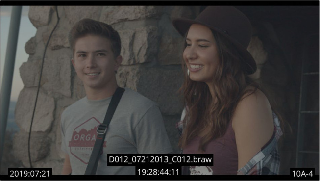
The resulting Burn-In fields on the frame
TIP: To use a logo image in a burn-in field, add a logo metadata from the left column. Then click the Import button in the Overlay Controls to select the image. You can reposition the image using the rest of the Overlay Controls.
Searchable Preferences and Project Settings
DaVinci Resolve 21 adds search bars to both the Preferences and Project Settings. This allows you to easily find a particular setting, without having to know where it is in the settings hierarchy.
To search, start to type the setting you wish to find in the search bar. As you type a list of possible matches will appear below. Click on the setting name you want and it will take you directly to that setting’s page. It will also briefly highlight the setting itself to make it easier to find.
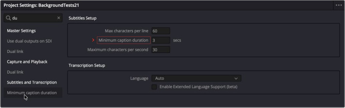
Start to type your setting in the search bar, and choose a the setting from the list below. It will take you to that setting’s page and highlight it to make it easy to find.
Multi User Projects Support Dynamic Project Switching
You can now use Dynamic Project Switching with multi-user projects. This allows you to copy/ paste between multiple projects instantly by loading all projects into RAM simultaneously. For more information on Dynamic Project Switching see Chapter 3, “Managing Projects and Project Libraries” in the DaVinci Resolve Reference Manual.
Up to 3x Faster File Sync Performance to Blackmagic Cloud
There is a significant three times increase in speed when syncing files to Blackmagic Cloud in DaVinci Resolve 21.
Codec Support
As always, each new version of DaVinci Resolve adds new codecs to support the latest cameras and technologies.
Enhanced, extended and faster MXF growing file support for broadcast workflows.
MXF OP1a support for MPEG-2 bitrate and other encode options.
Canon CR3 decode support and RAW control.
Fujifilm RAF decode support and RAW control.
Apple ProRAW decode support.
Improved Nikon NEF decode support.
Improved Sony ARW decode support.
Improved EXIF metadata support for stills formats.
HDR Vivid supplementary IMF ISXD package support.
MainConcept H.265 and MV-HEVC 4:2:0 and 4:2:2 encode support.
Intel QuickSync H.264 4:2:2 and AVC intra decode support.
Intel QuickSync AV1 4:4:4 encode support.
MV-HEVC decode support on Nvidia systems.
Encode support for multi-output audio only ambisonic formats.
Windows ARM H.265 4:2:2 10 bit decode support for DaVinci Resolve
Per render job option to override RCM or ACES outputs.
HEIF encode support on macOS and Windows.